Table of Contents
Advertisement
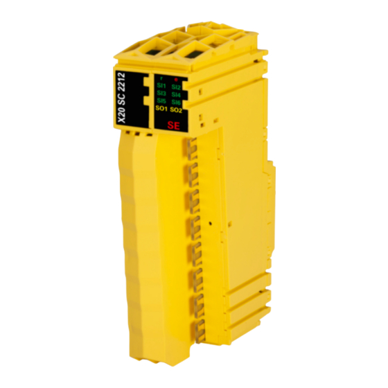
X20(c)SC2212
Information:
B&R makes every effort to keep data sheets as current as possible. From a safety point of view, how-
ever, the current version of the data sheet must always be used.
The certified, currently valid data sheet can be downloaded from the B&R website
tion.com.
Organization of notices
Safety notices
Contain only information that warns of dangerous functions or situations.
Signal word
Danger!
Warning!
Caution!
Notice!
General notices
Contain useful information for users and instructions for avoiding malfunctions.
Signal word
Information:
1 General information
The modules are equipped with 6 safe digital inputs and 2 safe digital outputs. They are designed for a nominal
voltage of 24 VDC.
The modules can be used to read in digital signals and control actuators in safety-related applications up to PL
e or SIL 3.
The modules are equipped with filters that are individually configurable for switch-on and switch-off behavior. The
modules also provide pulse signals for diagnosing the sensor line.
The outputs are designed using semiconductor technology so that the safety-related characteristics do not depend
on the number of switching cycles. The "high-side high-side" variant (output type B) is required for actuators with
reference potential (e.g. enable inputs on frequency inverters). It is important to observe the special notices for
the wiring in this case. Safe digital output modules are equipped with protection against automatic restart in the
event of network errors.
These modules are designed for X20 16-pin terminal blocks.
• 6 safe digital inputs, sink circuit
• 6 pulse outputs
• Software input filter configurable for each channel
• 2 safe digital outputs, output type B with 0.5 A, source circuit
• Integrated output protection
Data sheet V1.141 X20(c)SC2212 Translation of the original documentation
Description
Failure to observe these safety guidelines and notices will result in death, severe injury or substantial damage to property.
Failure to observe these safety guidelines and notices can result in death, severe injury or substantial damage to property.
Failure to observe these safety guidelines and notices can result in minor injury or damage to property.
Failure to observe these safety guidelines and notices can result in damage to property.
Table 1: Organization of safety notices
Description
Useful information, application tips and instructions for avoiding malfunctions.
Table 2: Organization of general notices
X20(c)SC2212
www.br-automa-
1
Advertisement
Table of Contents


Need help?
Do you have a question about the X20cSC2212 and is the answer not in the manual?
Questions and answers