Table of Contents
Advertisement
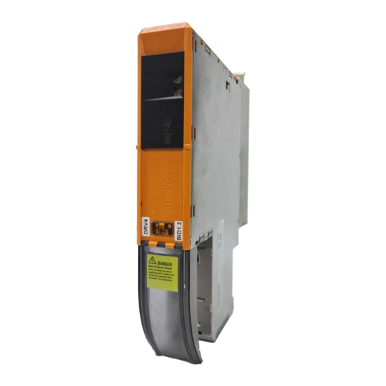
8BVI0014HWD0.000-1
1 General information
• Uncontrolled and safe stops integrated
• Integrated connection for motor holding brake and temperature sensor
• 2 slots for ACOPOSmulti plug-in modules
• 2-axis modules contain two complete standalone inverters in one inverter module
2 Order data
Model number
Short description
Wall mounting
8BVI0014HWD0.000-1
ACOPOSmulti inverter module 1.9 A, HV, wall mounting, 2 axes
Required accessories
Terminal block sets
8BZVI0055D0.000-1A
Screw clamp set for ACOPOSmulti 8BVI00xxHxD0 modules: 1x
8TB2112.2010-00, 1x 8TB2108.2010-00, 1x 8TB2104.203L-00,
1x
8TB3104.204K-11
8BZVI0055D0.500-1A
50x
multi modules 8BVI00xxHxD0: 1x 8TB2112.2010-00, 1x
8TB2108.2010-00, 1x 8TB2104.203L-00, 1x 8TB2104.203F-00,
1x 8TB3104.204G-11, 1x 8TB3104.204K-11
8BZVI0055D0.A00-1A
100x Screw clamp terminal block set for ACOPOS-
multi modules 8BVI00xxHxD0: 1x 8TB2112.2010-00, 1x
8TB2108.2010-00, 1x 8TB2104.203L-00, 1x 8TB2104.203F-00,
1x 8TB3104.204G-11, 1x 8TB3104.204K-11
Optional accessories
Accessory sets
8BXB000.0000-00
ACPmulti accessory set for encoder buffering consisting of: 1
lithium battery AA 3.6 V; 1 protective cap for battery holder
Fan modules
8BXF001.0000-00
ACOPOSmulti fan module, replacement fan for ACOPOSmulti
modules (8BxP / 8B0C / 8BVI / 8BVE / 8B0K)
Plug-in modules
8BAC0120.000-1
ACOPOSmulti plug-in module, EnDat 2.1 interface
8BAC0120.001-2
ACOPOSmulti plug-in module, EnDat 2.2 interface
8BAC0121.000-1
ACOPOSmulti plug-in module, HIPERFACE interface
8BAC0122.000-1
ACOPOSmulti plug-in module, resolver interface 10 kHz
8BAC0123.000-1
ACOPOSmulti plug-in module, incremental encoder and SSI ab-
solute encoder interface for RS422 signals
8BAC0123.001-1
ACOPOSmulti plug-in module, incremental encoder interface for
5 V single-ended and 5 V differential signals
8BAC0123.002-1
ACOPOSmulti plug-in module, incremental encoder interface for
24 V single-ended and 24 V differential signals
8BAC0124.000-1
ACOPOSmulti plug-in module, SinCos interface
8BAC0125.000-1
ACOPOSmulti plug-in module, SinCos EnDat 2.1/SSI interface
8BAC0130.000-1
ACOPOSmulti plug-in module, 2 digital outputs, 50 mA, max.
62.5 kHz, 2 digital outputs, 500 mA, max. 1.25 kHz, 2 digital
inputs 24 VDC
8BAC0130.001-1
ACOPOSmulti plug-in module, 2 digital outputs, 50 mA, max.
62.5 kHz, 4 digital outputs, 500 mA, max. 1.25 kHz
8BAC0132.000-1
ACOPOSmulti plug-in module, 4 analog inputs ±10 V
8BAC0133.000-1
ACOPOSmulti plug-in module, 3 RS422 outputs for ABR en-
coder emulation, 1 Mhz
POWERLINK cable
X20CA0E61.00020
POWERLINK connection cable, RJ45 to RJ45, 0.2 m
X20CA0E61.00025
POWERLINK connection cable, RJ45 to RJ45, 025 m
X20CA0E61.00030
POWERLINK connection cable, RJ45 to RJ45, 03 m
X20CA0E61.00035
POWERLINK connection cable, RJ45 to RJ45, 035 m
X20CA0E61.00050
POWERLINK connection cable, RJ45 to RJ45, 0.5 m
X20CA0E61.00100
POWERLINK connection cable, RJ45 to RJ45, 1 m
Shield component sets
8SCS000.0000-00
ACOPOSmulti shield component set: 1 shield plate 1x type 0, 1
hose clamp, B 9 mm, D 12-22 mm
8SCS002.0000-00
ACOPOSmulti shield component set: 1x clamping plate; 2x
clamps D 4-13.5 mm; 4x screws
Data sheet V 1.4
8TB2104.203F-00,
1x
8TB3104.204G-11,
Screw
clamp
terminal
block
Table 1: 8BVI0014HWD0.000-1 - Order data
1x
set
for
ACOPOS-
8BVI0014HWD0.000-1
Figure
1
Advertisement
Table of Contents

Subscribe to Our Youtube Channel
Related Manuals for B&R 8BVI0014HWD0.000-1


Summary of Contents for B&R 8BVI0014HWD0.000-1
-
Page 1: General Information
ACOPOSmulti shield component set: 1 shield plate 1x type 0, 1 hose clamp, B 9 mm, D 12-22 mm 8SCS002.0000-00 ACOPOSmulti shield component set: 1x clamping plate; 2x clamps D 4-13.5 mm; 4x screws Table 1: 8BVI0014HWD0.000-1 - Order data Data sheet V 1.4... -
Page 2: Technical Data
ACOPOS P3 Schirmkomponentenset: 1x Klemmbügelblech; 2x Klemmbügel D 4-13,5 mm; 2x Schrauben 8SCSE02.0200-00 ACOPOS P3 Schirmkomponentenset: 1x Klemmbügelblech; 2x Klemmbügel D 4-13,5 mm; 2x Schrauben Table 1: 8BVI0014HWD0.000-1 - Order data 3 Technical data Model number 8BVI0014HWD0.000-1 General information B&R ID code... - Page 3 <5 V High >15 V Input current at nominal voltage Approx. 10 mA Switching delay Rising edge 52 µs ±0.5 µs (digitally filtered) Falling edge 53 µs ±0.5 µs (digitally filtered) Table 2: 8BVI0014HWD0.000-1 - Technical data Data sheet V 1.4...
- Page 4 Approx. 2.8 kg Module width Table 2: 8BVI0014HWD0.000-1 - Technical data Achievable safety classifications (safety integrity level, safety category, performance level) are documented in the user's manual (section "Safety technology"). Valid in the following conditions: 750 VDC DC bus voltage, 5 kHz switching frequency, 40°C ambient temperature, installation elevation <500 m above sea level, no derating due to cooling type.
- Page 5 8BVI0014HWD0.000-1 4 Status indicators Status indicators are located on the black cover of each module. Encoder SLOT1 Encoder SLOT2 Status of backup battery Power supply POWERLINK Inverter axis 1 Inverter axis 2 Figure 1: Indicator groups for 8BVI inverter modules (2-axis modules)
- Page 6 8BVI0014HWD0.000-1 4.1 RDY, RUN, ERR (8BVI, 8BVP, 8B0P) - LED status indicators Label Color Function Description Green Ready Solid green The module is operational and the power stage can be enabled (operating sys- tem present and booted, no permanent or temporary errors).
- Page 7 8BVI0014HWD0.000-1 4.4 Status changes when booting the operating system loader The following timing is used for the LED status indicators: Block size: 50 ms Repeats after: 3,000 ms Status Indicator 1. Boot procedure for base hardware active 2. Network configuration active 3.
- Page 8 8BVI0014HWD0.000-1 5 Dimension diagram and installation dimensions Permitted mounting orientations Hanging vertically Lying horizontally Impermissible mounting orientations Standing horizontally Hanging horizontally Figure 2: Dimension diagram and installation dimensions n... Number of slots on the mounting plate For proper air circulation, at least 60 mm clearance must be available above the mounting plate as well as below the module.
- Page 9 8BVI0014HWD0.000-1 6 Wiring 6.1 Pinout overview - Two-axis modules (single-width) +24 V Slot1 Slot2 12...EnDat 12...EnDat 6...Resolver 6...Resolver ACOPOSmulti 8BVI0014HxD0.000-1 8BVI0028HxD0.000-1 8BVI0055HxD0.000-1 Figure 3: Pinout overview - 8BVI0014HxD0.000-1, 8BVI0028HxD0.000-1, 8BVI0055HxD0.000-1 Data sheet V 1.4...
- Page 10 8BVI0014HWD0.000-1 6.1.1 X1 connector - Pinout Name Function Enable 1 Axis 2: Enable 1 COM (1) Axis 2: Enable 1 0 V Enable 2 Axis 2: Enable 2 COM (3) Axis 2: Enable 2 0 V S1/B+ Axis 2: Brake + / Activation of the external holding brake...
- Page 11 8BVI0014HWD0.000-1 6.1.3 X3A, X3B connectors - Pinout X3A, X3B Name Function Receive signal RXD\ Receive signal inverted Transmit signal Shield Shield Shield Shield TXD\ Transmit signal inverted Shield Shield Shield Shield Table 10: X3A, X3B connectors - Pinout 6.1.4 X4A connector - Pinout...
- Page 12 8BVI0014HWD0.000-1 6.1.5 Pinout - X4B plug Name Function Axis 2: Temperature sensor - Axis 2: Temperature sensor + B-/S2 Axis 2: Brake - / Activation of the external holding brake 1) 2) B+/S1 Axis 2: Brake + / Activation of the external holding brake...
- Page 13 8BVI0014HWD0.000-1 6.1.7 X5B connector - Pinout Name Function Axis 2: Protective ground conductor Axis 2: Motor connection W Axis 2: Motor connection V Axis 2: Motor connection U Table 14: X5B connector - Pinout 6.1.8 Input/output circuit diagram Figure 4: Enable...
- Page 14 8BVI0014HWD0.000-1 Figure 5: Holding brake Plug-in module 8BAC0120.000-1 8BAC0121.000-1 8BAC0122.000-1 8BAC0123.00x-1 8BAC0124.000-1 8BAC0125.000-1 Plug-in module 8BAC0120.000-1 8BAC0121.000-1 8BAC0122.000-1 8BAC0123.00x-1 8BAC0124.000-1 8BAC0125.000-1 Figure 6: Temperature sensor Data sheet V 1.4...
- Page 15 8BVI0014HWD0.000-1 Figure 7: Motor Data sheet V 1.4...
Need help?
Do you have a question about the 8BVI0014HWD0.000-1 and is the answer not in the manual?
Questions and answers