
Subscribe to Our Youtube Channel
Related Manuals for Peak PCAN-Diag 2


Summary of Contents for Peak PCAN-Diag 2
- Page 1 PCAN-Diag 2 Handheld Device for CAN Bus Diagnostics User Manual Document version 2.8.0 (2019-06-19)
- Page 2 Low-speed CAN transceiver Single-wire CAN transceiver PCAN® is a registered trademark of PEAK-System Technik GmbH. CANopen® and CiA® are registered community trade marks of CAN in Automation e.V. All other product names in this document may be the trademarks or registered trade- marks of their respective companies.
-
Page 3: Table Of Contents
PCAN-Diag 2 – User Manual Contents Introduction Properties at a Glance Scope of Supply Putting the Device into Operation CAN Connection (D-Sub) 2.1.1 Auxiliary Supply for CAN Transceiver 2.1.2 Ground Connection Voltage Supply 2.2.1 Supply Socket 2.2.2 Batteries Operation with the Push Dial 2.3.1... - Page 4 PCAN-Diag 2 – User Manual 3.1.15 Transceiver CAN Traffic Displaying Incoming CAN Messages Representing CAN Messages in Symbolic Form Managing Symbol Files 4.3.1 Creating a Symbol File with the PCAN Symbol Editor 4.3.2 Using Multiplexers in Symbol Files 4.3.3 Reducing a Symbol File's Size...
- Page 5 PCAN-Diag 2 – User Manual 6.7.2 Fixing Decoding Problems Showing a Report about the Decoded CAN Frame Configurable Function F1 6.9.1 Saving the Scope Screen and the Sample Buffer Contents 6.9.2 Controlling the First Transmit List 6.10 Settings for the Oscilloscope Function 6.10.1...
- Page 6 PCAN-Diag 2 – User Manual 11 USB Connection with a PC 11.1 Unplugging the USB Connection 11.2 Purposes of the USB connection 11.3 Restriction for Diag Functions 11.4 PCAN-Diag Files on the Internal Memory Card 12 Technical Specifications Appendix A...
- Page 7 PCAN-Diag 2 – User Manual Menu Tree Device Settings Scope Silent startup Zoom Detect CAN bitrate Delay CAN bitrate User CAN bitrates Level CAN termination C1 C2 Transceiver mode Offs1 Offs2 Listen-only mode Single Auto-reset on BusOff Run/Stop D-Sub GND connection...
- Page 8 PCAN-Diag 2 – User Manual Elements on the Rear CAN connection (D-Sub) PC connection (USB) on page 13 on page 99 BNC connector for trigger output or for Ground socket measuring channel 2 on page 98 on page 95 Supply socket...
-
Page 9: Introduction
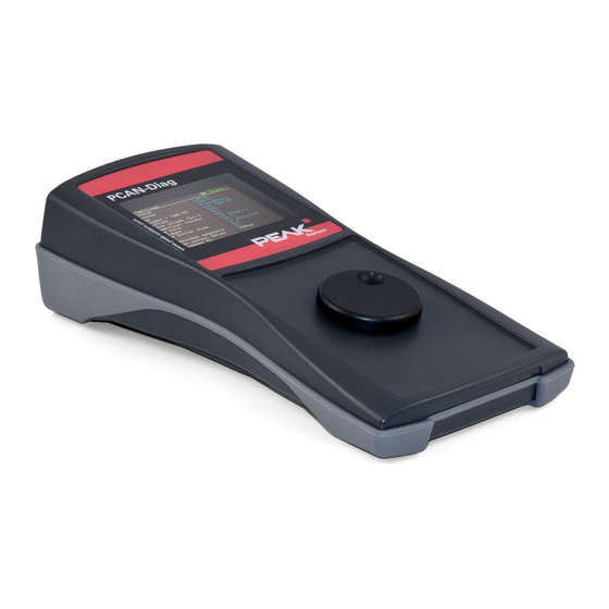
PCAN-Diag 2 – Introduction Introduction The PCAN-Diag 2 is a handheld diagnostics unit with functions to allow investigation of a CAN bus, such as detection of the CAN bitrate, bus load measurement, and termination measurement. As well as receiving CAN messages, it can transmit either individual messages or entire sequences of them. -
Page 10: Properties At A Glance
PCAN-Diag 2 – Introduction Properties at a Glance General High-speed CAN ISO 11898-2, available on request with CAN transceiver module for Low-speed CAN ISO 11898-3 or Single- wire CAN SAE J2411 CAN bus connection via D-Sub, 9-pin (in accordance with CiA®... - Page 11 PCAN-Diag 2 – Introduction Transmission of CAN messages or message lists Decimal, hexadecimal, or binary entering of CAN data; data change of a single transmission message during runtime Measurement of CAN bus load, displayed by means of a time diagram, switchable display of error frames...
-
Page 12: Scope Of Supply
Device configuration, transmit lists, and associated symbol files can be saved in projects Projects can be transferred to the internal memory card of the PCAN-Diag 2 using a USB connection Scope of Supply PCAN-Diag 2 Configuration software PCAN-Diag Editor for Windows... -
Page 13: Putting The Device Into Operation
PCAN-Diag 2 – Putting the Device into Operation Putting the Device into Operation For operation of the PCAN-Diag, go through the sections of this chapter in order. CAN Connection (D-Sub) CAN connector (D-Sub) on the rear of the device Depending on the equipped CAN transceiver, PCAN-Diag's CAN socket (9-pin D-Sub) has different pin assignments. -
Page 14: Auxiliary Supply For Can Transceiver
PCAN-Diag 2 – Putting the Device into Operation Pin assignment for equipment with Single-wire CAN transceiver (additional notes in the following subsections) 2.1.1 Auxiliary Supply for CAN Transceiver If the PCAN-Diag is equipped with a Low-speed or a Single-wire CAN transceiver, a supply for the CAN transceiver must be set up via pin 9 of the D-Sub connector in addition to the common voltage supply (section 2.2), otherwise the CAN communication does not... -
Page 15: Voltage Supply
PCAN-Diag 2 – Putting the Device into Operation Note: If the device is equipped with a Low-speed or a Single- wire CAN transceiver, GND must always be connected (refe- rence potential for the auxiliary supply), otherwise the CAN communication does not work. -
Page 16: Supply Socket
PCAN-Diag 2 – Putting the Device into Operation Note: Inserted rechargeable batteries are not charged during external supply. 2.2.1 Supply Socket Supplying the PCAN-Diag via the designated socket can be done using the enclosed AC adaptor or another DC source. - Page 17 PCAN-Diag 2 – Putting the Device into Operation The battery compartment is located on the device's bottom side. The lid is fixed with two screws. Positions of the screws for the lid of the battery compartment (second screw is located beneath the rubber sleeve) If an external supply is connected to the device, it will be used as primary source.
-
Page 18: Operation With The Push Dial
PCAN-Diag 2 – Putting the Device into Operation Operation with the Push Dial Operating the PCAN-Diag is solely done by the push dial. Dial: Push: Move selection; alter Switch on device; value execute selected function; exit current function 2.3.1 Powering Up the PCAN-Diag Hold down the push dial for at least half a second. -
Page 19: Switch Interlock
PCAN-Diag 2 – Putting the Device into Operation 2.3.2 Switch Interlock Powering up the device can be blocked by a small switch on the rear in order to prevent the batteries from accidental discharging, e.g. during transport. Switch on the rear of the device for switch interlock of the push dial,... -
Page 20: Status Indication
PCAN-Diag 2 – Putting the Device into Operation Do the following to set the date and time: In the main menu select Device Settings At the entry click on Set. Date & time and at click on the digits to be adjusted and... - Page 21 PCAN-Diag 2 – Putting the Device into Operation Icon Meaning The device operates in observation mode (listen-only). It is automati- cally activated if the silent startup function detects a difference between the bitrates of the device and on the bus ( ).
-
Page 22: Device Settings
PCAN-Diag 2 – Device Settings Device Settings Main menu entry Device Settings Here you specify the settings for the connection to a CAN bus and those for the use of the device. When you have changed settings, save them permanently with Save&OK. -
Page 23: Detect Can Bitrate
PCAN-Diag 2 – Device Settings after a short period, else it stays active. You can activate or deactivate the listen-only mode manually with the corresponding device setting Listen-only mode 3.1.2 Detect CAN bitrate If the bitrate of the CAN bus connected to the PCAN-Diag is un- known, the PCAN-Diag can automatically detect it. -
Page 24: Can Termination
PCAN-Diag 2 – Device Settings settings are analog to those of a SJA1000 CAN controller operating at 16 MHz clock frequency. Eight user-defined entries can be edited. Each entry contains a 2- byte value (4 hexadecimal digits) for the bus timing registers and an arbitrary name. - Page 25 PCAN-Diag 2 – Device Settings High-speed CAN Indication Transceiver: High speed A High-speed CAN bus needs to be electrically terminated on both ends using resistors of 120 . If the PCAN-Diag is connected to an un-terminated end of a CAN bus, the internal terminating resistor of 124 ...
-
Page 26: Transceiver Mode
PCAN-Diag 2 – Device Settings Single-wire CAN Indication Transceiver: Single wire The busload resistor at the Single-wire CAN transceiver can be changed with this function. Setting Resistor 9.1 k 2.1 k For more information about the function of the busload resistor, see the data sheet of the TH8056 CAN transceiver by Melexis (www.melexis.com), for example. -
Page 27: Listen-Only Mode
PCAN-Diag 2 – Device Settings 3.1.7 Listen-only mode If you want the device to not affect the traffic on the CAN bus, i.e. use it as pure monitoring tool, the Listen-only mode must be acti- vated ( On). The device will neither acknowledge nor transmit CAN (error) frames. -
Page 28: Screensaver Timeout
PCAN-Diag 2 – Device Settings 3.1.11 Screensaver timeout The brightness of the display will be reduced whenever the device is not operated for a certain period. This can prolong the operating time at use with (rechargeable) batteries. 3.1.12 Beeper The PCAN-Diag can give acoustic feedback to several events. -
Page 29: Can Traffic
Main menu item CAN Data The PCAN-Diag 2 can show the CAN data of incoming CAN messa- ges either in a simple way in hexadecimal format (section 4.1) or with the help of symbol files that convert the CAN data into a more readable form (sections 4.2/4.3 on page 32). - Page 30 PCAN-Diag 2 – CAN Traffic Simple view of incoming CAN messages. You can manipulate sorting in the table by clicking on CAN messa- ges. By doing so these messages are moved to the top of the list and marked orange. Clicking on an orange CAN message takes back the emphasis, meaning that is sorted by CAN ID again.
- Page 31 PCAN-Diag 2 – CAN Traffic Clears the list of incoming CAN messages and resets the CAN con- troller. Latter is useful after fault maintenance on the CAN bus. Tx1 … Tx7 These items represent the first seven transmit lists that are defined under >...
-
Page 32: Representing Can Messages In Symbolic Form
PCAN-Diag 2 – CAN Traffic Representing CAN Messages in Symbolic Form Menu item > CAN Data Receive Msgs. as Symbols In order to simplify the interpretation of CAN data, it can be repre- sented in symbolic form. The representation is determined by a symbol file. - Page 33 PCAN-Diag 2 – CAN Traffic Symbol Variables Symbolic representation of CAN messages, to be reached with > CAN Data Receive Msgs. as Symbols Sort Sorts the displayed symbols according to the selected element. Selection for sorting Meaning Symbol name Name...
-
Page 34: Managing Symbol Files
PCAN-Diag 2 – CAN Traffic Managing Symbol Files Menu item > CAN Data Manage Symbol Files With a symbol file the symbolic representation of CAN messages is determined. Using symbol files: One or more symbol files are made available in the PCAN-Diag by a project (more about projects in chapter 7 on page 85). -
Page 35: Creating A Symbol File With The Pcan Symbol Editor
PCAN-Diag 2 – CAN Traffic In the PCAN-Diag the symbol file to be used is selected, and it is determined which elements of this symbol file are displayed. SelectFile Shows a list of symbol files that are provided by the current project. - Page 36 PCAN-Diag 2 – CAN Traffic After starting the program, the folders in the Item Navigator on the left hand side are still empty. Click on Add Symbol. A new entry appears in the Symbols folder of the Item Navigator. Adjust the items in the Symbol properties panel according...
- Page 37 PCAN-Diag 2 – CAN Traffic Adjustments are done for the marked items. Click on Add Variable. As before with the symbol, adjust the items according to the given values for the Speed variable. Repeat the previous step for the Temperature variable.
- Page 38 PCAN-Diag 2 – CAN Traffic In order to display negative values the Data Type must be set to Signed. With Add Enum create the Switches enum. Later on this is used for the Switch1 variable. A new entry appears in the Enums folder of the Item Navigator.
- Page 39 PCAN-Diag 2 – CAN Traffic The variable uses the Switches enum. Use Save as to save the symbol file with the name SymExample.sym. The final symbol file has the following contents: FormatVersion=5.0 // Do not edit! Title="Example" {ENUMS} enum Switches(0="Off", 1="On")
-
Page 40: Using Multiplexers In Symbol Files
PCAN-Diag 2 – CAN Traffic 4.3.2 Using Multiplexers in Symbol Files With multiplexers different symbol definitions are used for the representation of CAN data from a single message. An area of the CAN data is defined as multiplexer. The contained value indicates the symbolic representation to be used for the rest of the data in the CAN message. - Page 41 PCAN-Diag 2 – CAN Traffic Click on Add Symbol. Adjust the items in the Symbol properties panel according to the given values for the MuxSym symbol. The data length is not relevant at this point. It is determined later separately for each multiplexer.
- Page 42 PCAN-Diag 2 – CAN Traffic Add two multiplexers to the symbol by using Add Multiplexer. Multiplexer2 gets the value 01h (field Multiplexer Value). When the symbol file is used in the PCAN-Diag, the multi- plexers are treated as a single signal named Mux. The names given in the PCAN-Symbol Editor are dismissed.
- Page 43 PCAN-Diag 2 – CAN Traffic Add the Speed variable to Multiplexer1 by using Add Variable and adjust the entries according to the shown example. Add the Engine variable to Multiplexer2 by using Add Variable and adjust the entries according to the shown...
- Page 44 PCAN-Diag 2 – CAN Traffic Add the Temperature variable to each of the two multi- plexers by using Add Variable and adjust the entries according to the shown example. Use Save as to save the symbol file with the name MuxSymExample.sym.
- Page 45 PCAN-Diag 2 – CAN Traffic Common view of all variables Separate view of the multiplexers In the common view, the variables of all multiplexers are shown in a single list. If the given name and all parameters of a variable are identical for all multiplexers, this variable is only listed once.
-
Page 46: Reducing A Symbol File's Size
PCAN-Diag 2 – CAN Traffic 4.3.3 Reducing a Symbol File's Size Because of the limited working memory in the PCAN-Diag, symbol files can only be read up to a specific size (see also beginning of section 4.3 on page 34). One possibility to reduce the size of a symbol file is using the Display Mode property. -
Page 47: Transmitting Can Messages
PCAN-Diag 2 – CAN Traffic Transmitting CAN Messages Menu item > CAN Data Transmit Messages The transmission of CAN messages is done with transmit lists that have been created either with the menu command Manage (see following section) or with the Windows Transmit Lists program PCAN-Diag Editor. - Page 48 PCAN-Diag 2 – CAN Traffic There are columns for hexadecimal, decimal, and binary represen- tation for each data byte of the CAN message where the values can be altered. You alter the value of a data byte by clicking on the value in either the...
-
Page 49: Managing Transmit Lists
PCAN-Diag 2 – CAN Traffic Managing Transmit Lists Menu item > CAN Data Manage Transmit Lists This function shows an overview of all available transmit lists. An enabled entry is marked with a cross [X]. This means that the... - Page 50 PCAN-Diag 2 – CAN Traffic Modify the list's name by clicking on it. Characters are deleted with Keep the push dial pushed for automatic repetition. By default, the list already contains one entry. With the mnemonics on the right you can do following actions:...
-
Page 51: Recording Can Traffic
PCAN-Diag 2 – CAN Traffic The value in the column is indicating a duration in Offset milliseconds whereafter the CAN message is transmitted. The offset refers to the previously transmitted CAN message, thus this is a relative designation. Note the given value for Min. - Page 52 PCAN-Diag 2 – CAN Traffic If required, the incoming CAN traffic can be filtered due to CAN IDs (see the following section 4.7 on page 53). Note: When invoking the function and during the recording of the incoming CAN traffic, the transmission of CAN messages is suspended.
-
Page 53: Filtering The Can Traffic (At Recording)
PCAN-Diag 2 – CAN Traffic Filtering the CAN Traffic (at Recording) Usually all incoming CAN messages are used for CAN recording. They can be filtered by a list of permissible CAN IDs. A filter list is defined in a text file called Filter.flt that is placed in the directory of the desired project on the internal memory card. -
Page 54: Example Filter.flt
PCAN-Diag 2 – CAN Traffic For performance reasons, it is recommended to list CAN IDs in rising order. A comment can be inserted starting with a double slash. Section/Keyword Description Example entries [global] This section is obligatory and must contain the following two keywords. -
Page 55: Playing Back Recorded Can Traffic
PCAN-Diag 2 – CAN Traffic 0x7f0-0x7fe [single_29bit] 0x123 0x11111 125000 // = 0x1E848 [range_29bit] 500-550 0x9000-0x10000 0x1F80000-0x1FA0000 Playing Back Recorded CAN Traffic Menu item > CAN Data Play Back Trace The PCAN-Diag can play back CAN messages from a binary trace file (*.btr) onto the connected CAN bus. -
Page 56: Using The Recorded Can Traffic On The Pc
For further use you must convert the data in an appropriate format. The Windows program PEAK-Converter is supplied on the DVD and on the internal memory card of PCAN-Diag for this purpose. - Page 57 Diag, we recommend using the format version 1.1., because the recordings of the PCAN-Diag only have one channel and because this format version is usable in all programs from PEAK-System. Vector ASC Trace .asc Text-based trace format by the Vector company that also can be used by some third-party programs.
-
Page 58: Measuring Functions For The Can Bus
PCAN-Diag 2 – Measuring Functions for the CAN Bus Measuring Functions for the CAN Bus Main menu item Measurements This chapter describes the measurement functions of the PCAN- Diag. The oscilloscope function is covered in the following chapter 6 on page 65. - Page 59 PCAN-Diag 2 – Measuring Functions for the CAN Bus Bus load diagram with message bursts (red peaks) You can counter a high bus load with the following measures: Raise the bitrate of all CAN nodes on the bus. Increase the cycle time of specific messages in the CAN net in order to reduce their emergence (less CAN messages per time).
- Page 60 PCAN-Diag 2 – Measuring Functions for the CAN Bus Errors Toggles between the view with and without the additional graph for occurring error frames (blue). Bus load diagram with error frames...
-
Page 61: Can Bus Termination
PCAN-Diag 2 – Measuring Functions for the CAN Bus CAN Bus Termination Menu item > Measurements CAN Termination Note: This function is only available if the PCAN-Diag is equipped with a High-speed CAN transceiver (indication at Device Settings Transceiver: High speed The function measures the resistance value between the CAN_L and CAN_H lines. - Page 62 PCAN-Diag 2 – Measuring Functions for the CAN Bus CAN termination Indicates the measured resistance value. Measurement Interpretation ~ 60 Ohm The termination at the CAN bus is ok in terms of measurement. Make sure that the termination resistors are positioned at each end of the bus and not, for example, at taps in the middle of the bus.
-
Page 63: Voltages On The D-Sub Connector
PCAN-Diag 2 – Measuring Functions for the CAN Bus Voltages on the D-Sub Connector Menu item > Measurements D-Sub Connector The voltage levels for each pin of the D-Sub connector are mea- sured and listed under in the table. On the basis of the... - Page 64 PCAN-Diag 2 – Measuring Functions for the CAN Bus Icon Voltage source Externally via supply socket (e.g. with the supplied AC adaptor) Inserted (rechargeable) batteries Settings Customize the view for each pin. Element Function Comment Arbitrary pin name Name Measurement and display...
-
Page 65: Oscilloscope Function
PCAN-Diag 2 – Oscilloscope Function Oscilloscope Function Main menu item Scope The oscilloscope function is used for in-depth diagnosis of the CAN signals on the connected lines. The handling of the function is similar to a standard storage scope. -
Page 66: Elements Of The Scope Screen
PCAN-Diag 2 – Oscilloscope Function Inspection of external signals (with frequencies up to 1 MHz) with a probe via the BNC connection Configuration of trigger to frame start, frame end, CAN errors, CAN ID, or to signal edges for external signals... -
Page 67: Adjusting The View
PCAN-Diag 2 – Oscilloscope Function Adjusting the View Functions Zoom, Delay, and With the following functions the current view on the horizontal axis (time axis) is adjusted. Element Function Zooming in or out horizontally. The reference point for zooming... - Page 68 PCAN-Diag 2 – Oscilloscope Function Note: The level triggering always refers to the measuring channel 2 (white signal course on the scope screen). Adjustment of the trigger level (orange line) If the current trigger level is above or below the viewable area of the Y axis, this is indicated by an orange arrow.
-
Page 69: Measuring A Time Period
PCAN-Diag 2 – Oscilloscope Function Indication of the trigger level on the right Measuring a Time Period Functions A section of the time axis can be marked on the screen with the two cursors C1 and C2 (vertical lines) in order to measure a time period. -
Page 70: Vertically Moving Curves
PCAN-Diag 2 – Oscilloscope Function Repeat the procedure with in order to set the end point of the time period. This must be positioned to the right of the start point. In the lower status bar read the length of the time period from t=. -
Page 71: Sampling Signals
PCAN-Diag 2 – Oscilloscope Function Sampling Signals Functions Single Run/Stop The sample buffer is filled with the signal course when a trigger event is recognized. To sample once, click on Single. Activate repeated sampling with Run. Stop the action with Stop. - Page 72 PCAN-Diag 2 – Oscilloscope Function Decoded signal course Additionally to the data in the CAN frame, the segments of the CAN frame can be displayed with markers in the signal course: Setting > > Show decoded segments Additional segment indication at decoding...
-
Page 73: Fixing Decoding Problems
PCAN-Diag 2 – Oscilloscope Function 6.7.2 Fixing Decoding Problems Decoding Meaning Possible measure(s) display Red data Faulty CAN frame Set the device's CAN bitrate to the one on the connected CAN bus: > Device Settings CAN bitrate > Device Settings... - Page 74 PCAN-Diag 2 – Oscilloscope Function This function is not available if the scope trigger is in Run mode. Click on and, if required, once or several times on Stop Single order to sample the desired CAN frame on the scope screen.
-
Page 75: Configurable Function F1
PCAN-Diag 2 – Oscilloscope Function Property Description ACK delay start Delays at the start and the end of the acknowledge ACK delay end sequence related to the nominal moments; percentage: delay related to a bit timing (depending on the bitrate). -
Page 76: Saving The Scope Screen And The Sample Buffer Contents
PCAN-Diag 2 – Oscilloscope Function 6.9.1 Saving the Scope Screen and the Sample Buffer Contents With the according configuration, saves the screen contents as bitmap (pict000.bmp) or the current sample buffer as CSV file (data000.csv) to the internal memory card. -
Page 77: Controlling The First Transmit List
PCAN-Diag 2 – Oscilloscope Function Contents Structure Time offset samples values [s] name;value Column name for the following sample values name;name;name CAN bitrate name;value Numbered sample values number;value;value Calculations for a sample value (in brackets: row): Time: Time(14+) * Timebase(10) + Time Offset(11) -
Page 78: Settings For The Oscilloscope Function
PCAN-Diag 2 – Oscilloscope Function 6.10 Settings for the Oscilloscope Function Menu item > Scope Setting 6.10.1 Ch1 source Selection of the signal source for the display of measuring channel 1 (green course). Note: The selection is depending on the CAN transceiver that is integrated in the PCAN-Diag. -
Page 79: Ch2 Source
PCAN-Diag 2 – Oscilloscope Function 6.10.2 Ch2 source Selection of the signal source for the display of measuring channel 2 (white course). Note: The selection is depending on the CAN transceiver that is integrated in the PCAN-Diag. Setting Description CAN_Low signal from the D-Sub connector (High-speed CAN,... -
Page 80: Trigger
PCAN-Diag 2 – Oscilloscope Function 6.10.3 Trigger Selection of the event that triggers the sampling of the signals (trigger event). Setting Description Trigger source Start of a recognized CAN frame FrameStart End of a recognized CAN frame FrameEnd Free-running sampling without trigger; the... -
Page 81: Auto Offset
PCAN-Diag 2 – Oscilloscope Function 6.10.5 Auto offset Setting Description Automatic vertical offset for the measuring channels 1 and 2 Manual adjustment of the offset on the scope screen with Offs1 Offs2 Note: When adjusting manually with or Offs2, an Offs1 activated auto-offset function is deactivated. -
Page 82: Sample Buffer Size
PCAN-Diag 2 – Oscilloscope Function 6.10.10 Sample buffer size Changes the buffer size and with this the sampling time. Smaller buffer sizes are useful for a faster repetition of the sampling run. The sampling time results from the quotient of the sample buffer size and the sample rate. -
Page 83: Trigger Output Delay
PCAN-Diag 2 – Oscilloscope Function Setting Description In addition to the data of the CAN frame, the segments of the CAN frame are displayed with markers in the signal course. Segment Designation in the CAN Description label specification 2.0 | (purple) -
Page 84: Function Key F1
PCAN-Diag 2 – Oscilloscope Function 6.10.14 Function key F1 Determines the action when is selected on the scope screen: Setting Description A bitmap screenshot of the scope screen is saved on the Save BMP internal memory card (file name: pict000.bmp with consecutive numbers). -
Page 85: Configuring The Device With Projects
PCAN-Diag 2 – Configuring the Device with Projects Configuring the Device with Projects Main menu item Projects With projects the PCAN-Diag can quickly be adapted to different applications. A project contains the following elements: Project element Assigned area in the PCAN-Diag... - Page 86 PCAN-Diag 2 – Configuring the Device with Projects Device-internal changes of the settings or of CAN transmit lists do not alter the affiliated project on the internal memory card. Load Project A project is selected from the internal memory card; the project's elements are loaded into the PCAN-Diag.
-
Page 87: Creating And Loading A Project
PCAN-Diag 2 – Configuring the Device with Projects Creating and Loading a Project The procedure from creation of a project to the use in the PCAN- Diag is divided into three phases: Creating a project on a PC with the Windows program PCAN- Diag Editor. - Page 88 PCAN-Diag 2 – Configuring the Device with Projects Adjust the settings for your application on the tabs Device Settings, Scope Settings, and D-Sub Connector. If needed, create one or more CAN Transmit Lists on the corresponding tab. The left panel contains the transmit lists, the right panel the CAN messages of a transmit list.
- Page 89 PCAN-Diag 2 – Configuring the Device with Projects Select the display type of multiplexers at the added symbol file, Target format column: Common Multiplexer: one list with all variables Separate Multiplexer: each multiplexer definition saparately Save the created project on a data carrier with the Save button The given file name is from now on used as project name.
- Page 90 PCAN-Diag 2 – Configuring the Device with Projects Click on Transfer to and check the PCAN-Diag device in the dialog box Select Devices. Tip: You can transfer the same configuration to several PCAN- Diag devices at the same time if those are connected to the PC.
- Page 91 PCAN-Diag 2 – Configuring the Device with Projects Click on OK. The project file (*.dpf) and the affiliated symbol files (*.sym, *.syb) are transferred to the PCAN-Diag (progress indicator Transfer data). The used directory on the internal memory card is /PCAN-Diag/Projects/<project name>.
-
Page 92: Integrating An Alternative Splash Screen
PCAN-Diag 2 – Configuring the Device with Projects Integrating an Alternative Splash Screen Each project can have an alternative splash screen in order to clarify already at startup which project is active. A bitmap file must be put into the corresponding project directory on the internal memory card. -
Page 93: Maintenance Functions For The Device
PCAN-Diag 2 – Maintenance Functions for the Device Maintenance Functions for the Device Main menu item Internal Statistics The page gives an overview about the device's internals. The specifications are usually used for support purposes. Furthermore, hardware functions are available for maintenance of the device. -
Page 94: Browsing The Internal Memory Card
PCAN-Diag 2 – Browsing the Internal Memory Card Browsing the Internal Memory Card Main menu item Memory Card The PCAN-Diag has functions to show directories and bitmaps from the internal memory card. Note: The PCAN-Diag cannot access the memory card as long as a USB connection to a PC is established. -
Page 95: 10 Bnc Connector
PCAN-Diag 2 – BNC Connector 10 BNC Connector BNC connector on the rear of the device The BNC connector is used in the oscilloscope function. The func- tion of the BNC connector depends on the setting for measuring channel 2 ( >... -
Page 96: Trigger Output
PCAN-Diag 2 – BNC Connector 10.1 Trigger Output Other measuring devices or oscilloscopes, e.g. not capable of CAN- specific measurements, can pick off a trigger signal that is evoked by the internal oscilloscope function of the PCAN-Diag. The trigger output is active if the measuring channel 2 (Ch2) of the oscilloscope function is set to the CAN input: >... -
Page 97: External Signal
PCAN-Diag 2 – BNC Connector 10.2 External Signal Instead of the CAN signal CAN_Low, the measuring channel 2 (Ch2) of the oscilloscope function can sample an external signal for inspection and trigger purposes coming from the BNC connector. Attention! The voltage of an external signal may have a maximum of ±50 V. -
Page 98: Ground Socket
PCAN-Diag 2 – BNC Connector 10.3 Ground Socket In order to establish a separate voltage ground connection between the PCAN-Diag and the measuring object, a ground socket (4 mm) is provided. GND socket (4 mm) on the rear of the device... -
Page 99: 11 Usb Connection With A Pc
PCAN-Diag 2 – USB Connection with a PC 11 USB Connection with a PC A USB connection to a PC is used for access to the internal memory card of the PCAN-Diag. The PC's operating system binds the memo- ry card into the file management, e.g. under Windows as mass storage device. -
Page 100: Purposes Of The Usb Connection
PCAN-Diag 2 – USB Connection with a PC 11.2 Purposes of the USB connection Transferring projects onto the memory card of the PCAN-Diag with the provided Windows program PCAN-Diag Editor Creating and Loading a Project (7.1 on page 87) Access to the trace, bitmap, or CSV files created by the PCAN-... -
Page 101: Pcan-Diag Files On The Internal Memory Card
PCAN-Diag 2 – USB Connection with a PC 11.4 PCAN-Diag Files on the Internal Memory Card Directory - file Function /PCAN-Diag/ Fixed storage branch for files that are accessed by the PCAN-Diag or that are related to the device Projects/<project Projects;... - Page 102 PCAN-Diag 2 – USB Connection with a PC Directory - file Function Software tools to be used with the PCAN-Diag (the Tools/ following only lists the executables) PcanDiagEdt.exe Windows program PCAN-Diag Editor for creating projects Windows program PCAN Symbol Editor for PcanSEdt.exe...
-
Page 103: 12 Technical Specifications
PCAN-Diag 2 – Technical Specifications 12 Technical Specifications Power supply Supply voltage Externally via supply socket: 12 V DC nominal, 8 - 50 V possible Internally with 4 (rechargeable) batteries (size AA): 4 x 1.5 V or 4 x 1.2 V DC Note: The device does not charge inserted rechargeable batteries. - Page 104 PCAN-Diag 2 – Technical Specifications BNC connector Functions Trigger output or signal input Trigger output Voltage idle state +3.3 V Voltage trigger event 0 V (falling edge) Pulse duration 4 CAN bit timings, actual duration depending on the set CAN bitrate (at 500 kbit/s: 4 * 2 μs = 8 μs)
- Page 105 PCAN-Diag 2 – Technical Specifications Internal memory card Size at least 1 GByte File system FAT32 Name of the USB device PCAN-DIAG Display Type Resolution 320 x 240 pixels Measures Size 103 x 58 x 212 (225 with BNC connector) mm...
-
Page 106: Appendix Ace Certificate
PCAN-Diag 2 – Appendix Appendix A CE Certificate... -
Page 107: Appendix B Dimension Drawing
PCAN-Diag 2 – Appendix Appendix B Dimension Drawing The figure does not show the original size; dimensions for case without rubber sleeve... -
Page 108: Appendix C Disposal Information (Batteries)
The device and the batteries it contains must not be disposed of with household waste. Remove the batteries from the device for proper separate disposal. The PCAN-Diag 2 contains the following batteries: 4 (rechargeable) batteries, size AA, 4 x 1.5 V or 4 x 1.2 V... -
Page 109: Appendix D Index
PCAN-Diag 2 – Appendix Appendix D Index CAN Termination (menu item) CAN traffic ACK signal filtering at recording delay measurement play back Chimes Acoustic feedback record act (status indication) CE certificate Chimes D-Sub measurement Batteries switch off disposal Configuration with a project... - Page 110 PCAN-Diag 2 – Appendix F1 (Scope) Observation mode File names activate reset index off (status indication) Files on the memory card Offs1 Offs2 (Scope) Filter for CAN IDs (at recording Offset Filter.flt vertical, for curve display example Operation format description...
- Page 111 PCAN-Diag 2 – Appendix Reset of the CAN controller T=0 (Scope) automatically Technical specifications possibilities Termination Run (Scope) measure set internal Thresholds for D-Sub measurement Sample buffer save contents Time Sample rate Time measurement signal course 69 adjust Trace Scope (menu item)
Need help?
Do you have a question about the PCAN-Diag 2 and is the answer not in the manual?
Questions and answers