
Related Manuals for ARMTEL TOP-PAD-IP2


Summary of Contents for ARMTEL TOP-PAD-IP2
- Page 1 TOP-PAD-IP2 Desktop intercom station RMLT.465329.001UM User Manual Document version 7 26.30.11.190 2020...
- Page 2 © Armtel info@armtel.com...
-
Page 3: Introduction
Desktop intercom station» RMLT.465329.001 manufactured by Armtel LLC, and is intended to familiarize the User with the device and the procedure for its operation at the installation site. Designed for organization of two-way communication as a component of IPN system manufactured by Armtel LLC. -
Page 4: Safety Provisions
TOP-PAD-IP2 DESKTOP INTERCOM STATION User Manual SAFETY PROVISIONS During installation and operation observe the safety measures specified by local codes and regulations on electrical safety. During installation and operation, observe safety precautions laid out in “Occupational safety rules when operating electrical installations” when working with electrical receivers with voltage of up to 1000 V. -
Page 5: Table Of Contents
TOP-PAD-IP2 DESKTOP INTERCOM STATION User Manual CONTENTS INTRODUCTION ..................................1 SAFETY PROVISIONS ................................2 CONTENTS ....................................3 1 DESCRIPTION AND OPERATION ..........................5 1.1 Product description and operation ........................5 1.1.1 Features ................................5 1.1.2 Main specifications ............................8 1.1.3 Operations conditions ..........................10 1.1.4 Design................................ - Page 6 Wall-mounting ....................... 52 APPENDIX D (reference) Turntable-mounting ....................57 APPENDIX E (reference) Recommendations on flush-mounting TOP-PAD-IP2 ........58 APPENDIX F (reference) TOP-PAD-IP2 indication types on display ............62 APPENDIX G (reference) Scope of supply ......................63 page 4/64 armtel.com © Armtel...
-
Page 7: Description And Operation
Address /General Alarm communication systems (based on allotted SIP server manufactured by LLC Armtel) at metal, chemical, oil-processing, oil and gas, energy and transport industries or at facilities of the same type. TOP-PAD-IP2 is designed for installation in control, office rooms and premises. - Page 8 − connection to the Ethernet network via wireless Wi-Fi (except for RMLT.465329.001-01 version); − recording and playback of voice messages on IPN terminal devices; − processing of calls priorities of the protocols SIP, “Armtel-IP”, and “Call cancel“ function; − organization of unilateral control mode in simplex intercom;...
- Page 9 − increasing of function keys total number up to 84 pcs. by connecting of up to two Expansion units TOP-EC-IP2 RMLT.468366.009. Configuration of TOP-PAD-IP2 shall be carried out using the personal computer of the IPN network administrator on which IPN2 RU.RMLT.00041-01 IPN Config Tool software configuration application is installed.
-
Page 10: Main Specifications
TOP-PAD-IP2 DESKTOP INTERCOM STATION User Manual 1.1.2 Main specifications Main specifications of TOP-PAD-IP2 are given in Table Table 1 – Main specifications (beginning) Parameter Value Electrical parameters Rated voltage PoE (IEEE 802.3at), V Supply voltage range PoE (IEEE 802.3at) at turn on, V 42…60... - Page 11 TOP-PAD-IP2 DESKTOP INTERCOM STATION User Manual Table 1 – Main specifications (continuation) Parameter Value Data lines 10BASE-T (IEEE802.3i) 100BASE-TХ (IEEE802.3u) Ethernet communication interface*** Channel bonding (IEEE802.3ad) Communication protocols via Ethernet SIP, «Armtel-IP» C (Armtel), Communication buses with auxiliary modules USB 2.0 Wireless communication interface Wi-Fi 2.4, 5.0...
-
Page 12: Operations Conditions
Ingress protection of TOP-PAD-IP2 complies wit IP42. TOP-PAD-IP2 complies with the requirements electromagnetic interference according to IEC 61000-6-2:2005, with not lower B quality criterion. The electromagnetic interference from TOP-PAD-IP2 does not exceed the codes specified in IEC 61000-6-4:2006. page 10/64 armtel.com ©... -
Page 13: Design
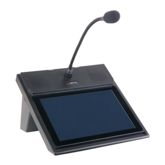
TOP-PAD-IP2 DESKTOP INTERCOM STATION User Manual 1.1.4 Design 1.1.4.1 The external appearance and overall dimensions of TOP-PAD-IP2 in desktop version and with G14-2 microphone are illustrated at Figure 1 – LED indication on the microphone; 2 – microphone; 3 – stand; 4 – built-in speakers;... - Page 14 100 meters from TOP-PAD-IP2 or more - depending on the characteristics of the antenna on the access point. The external appearance of Wi-Fi antenna is illustrated at...
- Page 15 Figure 5 – The plate with the designation of sockets for external connections 1.1.4.5 To ensure a reliable connection of TOP-PAD-IP2, cables, they can be placed in special grooves in the base of the enclosure (4 pcs.) and in the stand (2 pcs.) in accordance...
- Page 16 1.1.4.9 When using the “Ethernet bonding” function, in addition to the main cable Ethernet (Patch Cord) connected to RJ-45 socket on the base of TOP-PAD-IP2 enclosure, an additional Patch Cord should be connected to another RJ-45 socket in accordance with Figure 2.
-
Page 17: Labeling
− serial number and date of manufacture. The package is made according to the drawings of the product manufacturer and enables storage of the TOP-PAD-IP2, provided requirements set in Section 5 are met. For shipment of the TOP-PAD-IP2 from the manufacturer, consumer package contents are placed in the package place, which ensures protection from mechanical damage, direct ingress of atmospheric precipitation, dust and solar radiation during transportation. -
Page 18: Description And Operation Of The Product Components
− microphone; − speakers; − Wi-Fi module. 1.2.2 Main board TOP-PAD-IP2 main board is a printed board with installed electronic elements required for functioning of the TOP-PAD-IP2. External appearance of main board is given on Figure Figure 7 – TOP-PAD-IP2 main board (sockets side view) page 16/64 armtel.com... -
Page 19: Touch Screen Display
TOP-PAD-IP2 according to the algorithm assigned in the IPN Config Tool. The TOP-PAD-IP2 main board has the sockets that are connected to the enclosure base for connecting cables to the Ethernet network, Handset unit, the USB socket, and the external power supply socket. -
Page 20: Microphone
LED indication blinks with a period of about 0.6 seconds. 1.2.5 Built-in speakers В TOP-PAD-IP2 uses a wideband speaker manufactured by PUI Audio PUI Audio (see Figure 10) a rated power of 3 watts, with a moisture resistant paper diaphragm, with a nominal resistance of 8 ohms and a frequency response from 100 to 20,000 Hz with an average sound pressure level of 86 dB. -
Page 21: Wi-Fi Module
Figure 10 – External appearance and overall dimensions of built-in speaker 1.2.6 Wi-Fi module In the basic version of TOP-PAD-IP2 the Wi-Fi module WM1123WU is used, which is installed on the main board and supports IEEE 802.11a/b/g/n/ac protocol for operation at 2.4 GHz and 5.0 GHz with a bandwidth of up to 80 MHz. -
Page 22: Intended Use
1.1.3. 2.1.2 In case of PoE (PoE plus) power failure or connect two TOP-EC-IP2 Expansion units, it is necessary to supply TOP-PAD-IP2 with 12 V power from the external adapter via the socket at the base of the TOP-PAD-IP2 (see... -
Page 23: Preparation For Use
User Manual 2.2 Preparation for use Preparation of TOP-PAD-IP2 for use shall be carried out by the manufacturer’s representatives, or personnel trained to operate Armtel LLC products. The main preparation of the product for use is carried out during installation and connection. Preparation of TOP-PAD-IP2 for operation involves a series of steps: −... -
Page 24: Installation, Connection And Dismantling
2.4.1 The main installation position of TOP-PAD-IP2 is desktop mounting. With the desktop installation of TOP-PAD-IP2 on the base of the enclosure there is a stand for better visibility of the keys (see 1.1.4.2). If TOP-HS-IP2 Handset unit or TOP-EC-IP2 Expansion unit are used, in order to provide extra stiffness the modules can be attached to TOP-PAD-IP2 by aluminum junction plates supplied with additional modules. - Page 25 TOP-PAD-IP2 DESKTOP INTERCOM STATION User Manual 2.4.6 TOP-PAD-IP2 is dismantled in the following order: − disconnect microphone; − disconnect stand (if used); − disconnect all connection cables; − disconnect junction plates (if used); − in case turntable-mounting − remove the structure from the turntable and detach junction plates;...
-
Page 26: Operation
“IPN2 system configuration software” RU.RMLT.00041-01 IPN Config Tool is installed. Note − In addition to IPN Config Tool software, the TOP-PAD-IP2 can be configured by means of the embedded WEB interface which can also be used to update the software, download and save configuration files. -
Page 27: Graphical Interface
TOP-PAD-IP2 DESKTOP INTERCOM STATION User Manual 2.5.2 Graphical interface 2.5.2 TOP-PAD-IP2 panel is controlled with the graphical interface; the main panel of the graphical interface displays the following panels (see Figure 11): − informational panel (1), it contains the data on the current connection with a called subscriber, call queue, call history (incoming, outgoing, missed calls etc.);... - Page 28 TOP-PAD-IP2 DESKTOP INTERCOM STATION User Manual 2.5.2.2 The Information panel is comprised of the following fields: − current call information; − call queue; − call history. “Current call information” field displays the subscriber name and address as well as call time.
- Page 29 TOP-PAD-IP2 DESKTOP INTERCOM STATION User Manual 2.5.2.5 “Call Queue” tab is illustrated at Figure 12. 1 – information panel; 2 – modified control panel widgets. Figure 12 – “Call Queue” tab When you touch the key “Call Queue”, the information panel maximizes on the display, taking up the total space of the working field.
- Page 30 TOP-PAD-IP2 DESKTOP INTERCOM STATION User Manual 2.5.2.6 The algorithm of “History” tab, illustrated at Figure 13, is similar to “Call queue” tab. When you touch “History” key, the information panel maximizes on the display similarly “Call queue” tab, only in the maximized panel the information about last 25 subscribers with whom the connection has been established is displayed.
- Page 31 , enables the User to transfer a call to another subscriber with a direct key; − key «Conference» , enables the conference mode (see 2.5.4). 2.5.2.8 If TOP-PAD-IP2 is supplied with TOP-HS-IP2 Handset unit, «Telephone» tab is activated (see Figure 15).
- Page 32 TOP-PAD-IP2 DESKTOP INTERCOM STATION User Manual 1 – information panel; 2 – keypad panel. Figure 15 – Tab «Telephone» in the mode of making a call The information panel represents active connections and call history (incoming, outgoing, missed etc.). The direct keys in the main panel are converted into the function keys of the keypad.
- Page 33 2.5.2.10 The fixed keys block of the control panel at the top of the screen contains the following keys: «Settings», «Volume» и «No microphone». «Settings» key is used to transfer TOР-PAD-IP2 to control mode for the panel settings (see Figure 16): Figure 16 – “Settings” panel TOP-PAD-IP2 armtel.com page 31/64 info@armtel.com © Armtel...
-
Page 34: Assigning Virtual Keys To The Working Field Of The Panel
2.5.3 Assigning virtual keys to the working field of the panel Function keys (FK) are the virtual keys of the working field programmed to perform the communication function or local functions. TOP-PAD-IP2 keys function are configured from the Administrator personal computer using IPN Config Tool. The basic options for providing connection setup, maintenance and disconnection between subscribers are duplex settings (available values: «OFF», «Manual»... -
Page 35: Communication Types And Scenarios
2.5.4.1 TOP-PAD-IP2 supports two telecommunication protocols SIP (RFC 3261) and protocol “Armtel-IP”. The Desktop call station operation via SIP protocol can be carried out over SIP server. Calls via SIP protocols are made in both simplex and duplex modes, receiving of the calls - in half-duplex mode, and when using TOP-HS-IP2 Handset unit - in full duplex mode. - Page 36 TOP-PAD-IP2 DESKTOP INTERCOM STATION User Manual The participants of the circular are collected by the organizer of the circular with the help of FK “Circular”. After a short press on the FK with the function “Circular”, the organizer one by one presses the keys with the function “Call via SIP” of the subscribers to add new members to the circular or to remove participants from the circular.
- Page 37 ACM-IP2” RMLT.465275.006 produced by LLC Armtel. In this mode, activation of control lines on the ACM-IP2 does not occur, the module is free for voice calls. The control is carried out by FK with the assigned function “Relay”. The function works via protocol “Armtel-IP” and SIP.
-
Page 38: Troubleshooting
TOP-PAD-IP2 DESKTOP INTERCOM STATION User Manual 2.5.5 Troubleshooting Possible problems and solutions are given in Table Table 2 – Possible problems and solutions Problem Possible cause Solution Check that the cable connections are The screen is not lit, healthy and properly connected,... -
Page 39: Maintenance
− visual inspection of the incoming cables to TOP-PAD-IP2 (should not be compacted and have damage at the outer shell); − cleaning of TOP-PAD-IP2 surface from dirt, using for this purpose the wet sponge with mild soap solution or wet wipes for cleaning office appliances; the use of chemically active solvents is not admitted;... -
Page 40: Checking Operability
− pause for about 10 seconds to completely discharge the filtering power supply tanks in TOP-PAD-IP2; − apply power to TOP-PAD-IP2 again, make sure that the remote control is successfully initialized as described in 2.5.1. 3.4.2 Checking acoustic path... -
Page 41: Repair
TOP-PAD-IP2 DESKTOP INTERCOM STATION User Manual 4 REPAIR No scheduled repair work is provided for the product. Unscheduled repair shall be performed by the manufacturer at the request of the User. The place, time, procedure and cost of the work shall be agreed with the manufacturer in advance. -
Page 42: Appendix A (Reference) Connection
TOP-PAD-IP2 DESKTOP INTERCOM STATION User Manual APPENDIX A (REFERENCE) CONNECTION The pin assignment of RJ-45 sockets of TOP-DIS-IP2 Ethernet interface is given in Table A.1. Table А.1 – The pin assignment of RJ-45 sockets External appearance of RJ-45 socket Contact number... - Page 43 TOP-PAD-IP2 DESKTOP INTERCOM STATION User Manual The pin assignment of RJ-22 sockets for analog path connection of Handset unit is illustrated at Table A.2. А.2 - Table The pin assignment of RJ-22 sockets for analog path connection of TOP-HS-IP2 External appearance of RJ-22 socket...
- Page 44 TOP-PAD-IP2 DESKTOP INTERCOM STATION User Manual Requirements for connecting an external 12V adapter The external appearance of P1J socket for external 12 V adapter connection, dimensions and contact polarity are illustrated at Figure A.4. Figure A.4 – The appearance, dimensions and contact polarity of P1J socket page 42/64 armtel.com...
- Page 45 TOP-PAD-IP2 DESKTOP INTERCOM STATION User Manual An example of TOP-PAD-IP2 connection complete with TOP-HS-IP2 Handset unit is illustrated at Figure A.5. Figure A.5 – The example of TOP-PAD-IP2 connection armtel.com page 43/64 info@armtel.com © Armtel...
- Page 46 TOP-PAD-IP2 DESKTOP INTERCOM STATION User Manual The example of connection of TOP-PAD-IP2 complete with TOP-HS-IP2 Handset unit and “Ethernet bonding” function is illustrated at Figure A.6. The example of TOP-PAD Figure A.6 – -IP2 connection page 44/64 armtel.com © Armtel...
- Page 47 TOP-PAD-IP2 DESKTOP INTERCOM STATION User Manual The example of connection of TOP-PAD-IP2 complete with two TOP-EC-IP2 Expansion units, with TOP-HS-IP2 Handset unit is illustrated at Figure A.7. TOP-PAD-IP2 Desktop intercom station RJ-45 8P8C PJ-006A TOP-HS-IP2 Handset unit 12 VDC (connect two...
- Page 48 TOP-PAD-IP2 DESKTOP INTERCOM STATION User Manual The example of connection of TOP-PAD-IP2 complete with one or two TOP-EC-IP2 Expansion units is illustrated at Figure A.8. TOP-PAD-IP2 Desktop intercom station RJ-45 8P8C PJ-006A 12 VDC (connect two TOP-EC-IP2 TOP-EC-IP2) Expansion unit...
-
Page 49: Appendix B (Reference) Desktop Mounting Of The Unit Complete With Top-Hs-Ip2 Handset Unit And/Or Top-Ec-Ip2 Expansion Unit
TOP-PAD-IP2 DESKTOP INTERCOM STATION User Manual APPENDIX B (REFERENCE) DESKTOP MOUNTING OF THE UNIT COMPLETE WITH TOP-HS-IP2 HANDSET UNIT AND/OR TOP-EC-IP2 EXPANSION UNIT If TOP-HS-IP2 Handset unit is used, its installation set includes junction plates to impart stability and stiffen the assembly will be included into the scope of supply. The appearance... - Page 50 The TOP-HS-IP2 is connected to RJ-22 and RJ-25 sockets of the Desktop intercom station (see Figure A.5-A.7) via the connecting cables complete with TOP-HS-IP2. The design provides two mounting methods for TOP-HS-IP2 to TOP-PAD-IP2 Desktop intercom station: left-hand or right-hand (see Figure B.3).
- Page 51 RJ-25 sockets of the Desktop intercom station and the Expansion unit are connected with each other by the connecting complete with TOP-ЕС-IP2. TOP-EC-IP2 Expansion unit can be attached to TOP-PAD-IP2 Desktop call station from the left or from the right sides (see Figure B.6), connection accordance...
- Page 52 TOP-PAD-IP2 DESKTOP INTERCOM STATION User Manual Auxiliary Expansion units can be attached either directly to TOP-DIS-IP2, or to each other (see Figure B.7), connection accordance Figure A.8: Figure B.7 – The variants of adjustment of two TOP-EC-IP2 Expansion units page 50/64 armtel.com...
- Page 53 Figure A.7). Figure B.8 – The variants of TOP-HS-IP2 and TOP-EC-IP2 adjustment In all cases of desktop mounting of TOP-PAD-IP2 Desktop intercom station and options arrangements, upon completion of installation G14-2 removable gooseneck microphone should be attached to the unit.
-
Page 54: Wall-Mounting
TOP-PAD-IP2 DESKTOP INTERCOM STATION User Manual APPENDIX C (REFERENCE) WALL-MOUNTING To attach TOP-PAD-IP2 to the wall, the holes on the bottom side of the unit base stand should be used (see Figure C.1): Figure C.1 – Holes for TOP-PAD-IP2 mounting page 52/64 armtel.com... - Page 55 TOP-PAD-IP2 DESKTOP INTERCOM STATION User Manual At the place of installation, the layout is done in accordance with the template given (see Figure C.2): Figure C.2 − Layout on the wall for the brackets installation armtel.com page 53/64 info@armtel.com © Armtel...
- Page 56 C.3) by the screws provided and fixed to the wall through the holes (4). After fixing the brackets, the mounting plate is removed. Figure C.3 – Brackets for wall-mounting of TOP-PAD-IP2 In the holes 1, 4, 5, 8 on the bottom side of TOP-PAD-IP2 (see Figure C.1) 3 × 8 mm...
- Page 57 TOP-PAD-IP2 DESKTOP INTERCOM STATION User Manual If TOP-HS-IP2 should be supplied with TOP-PAD-IP2, it is fastened similar to desktop- mounting with junction plates provided. Layout on the wall for mounting TOP-PAD-IP2 with TOP-HS-IP2 is given at Figure C.4: Figure C.4 – Layout on the wall for mounting TOP-PAD-IP2 with TOP-HS-IP2 armtel.com...
- Page 58 TOP-PAD-IP2 DESKTOP INTERCOM STATION User Manual Layout on the wall for the mounting TOP-PAD-IP2 with TOP-HS-IP2 and with TOP-EC-IP2 is illustrated at Figure C.5. page 56/64 armtel.com © Armtel info@armtel.com...
-
Page 59: Turntable-Mounting
APPENDIX D (REFERENCE) TURNTABLE-MOUNTING For fixing TOP-PAD-IP2 to the turntable used holes on the underside of the bottom side. Mounting holes on the turntable and the bottom side of the remote control are combined and secured with 3x8 plastic screws provided. -
Page 60: Appendix E (Reference)
TOP-PAD-IP2 DESKTOP INTERCOM STATION User Manual APPENDIX E (REFERENCE) RECOMMENDATIONS ON FLUSH-MOUNTING TOP-PAD-IP2 In case of flush-mounting of TOP-PAD-IP2 the marking on the desktop should be carried out according to Figure E.1: Figure E.1 – Layout of the desktop for flush-mounting of TOP-PAD-IP2 page 58/64 armtel.com... - Page 61 TOP-PAD-IP2 DESKTOP INTERCOM STATION User Manual TOP-PAD-IP2 is flushed into the cut-out hole and fixed in holes 1-8 (see Figure E.2) by means of screws for ART 9091 plastic. Figure E.2 – Holes for self-tapping screws The permissible length of self-tapping screws should not exceed the value determined...
- Page 62 TOP-PAD-IP2 DESKTOP INTERCOM STATION User Manual If TOP-EC-IP2 Expansion unit should be attached to, the layout for its installation is fulfilled according to the dimensions illustrated at FigureE.1 and in accordance with Figure E.4: If the Desktop intercom station is equipped with TOP-HS-IP2, it should be mounted using self-tapping screws intended for plastic, similar to mounting of the Desktop intercom station, through two holes in the desktop with a diameter of 3.2 mm.
- Page 63 TOP-PAD-IP2 DESKTOP INTERCOM STATION User Manual at a distance (52 ± 0.2) mm from the outer holes for adjustment of the Desktop intercom station (see Appendix C of the User manual for TOP-HS-IP2 RMLT.465484.003) with horizontal and vertical marking. Both left-hand and right-hand options are available for the Handset unit mounting.
-
Page 64: Appendix F (Reference)
TOP-PAD-IP2 DESKTOP INTERCOM STATION User Manual APPENDIX F (REFERENCE) TOP-PAD-IP2 INDICATION TYPES ON DISPLAY TOP-PAD-IP2 indication types is given in Table F.1. Table F.1 – TOP-PAD-IP2 indication types Function Color Standstill Grey Incoming call (simplex / duplex) Green Missed call / notification of the second call... -
Page 65: Scope Of Supply
TOP-PAD-IP2 DESKTOP INTERCOM STATION User Manual APPENDIX G (REFERENCE) SCOPE OF SUPPLY Scope of supply of TOP-PAD-IP2 is given in Table G.1. Table G.1 – Scope of supply (beginning) Quanty- Identification Name Note ty, pcs. TOP-PAD-IP2 Desktop intercom RMLT.465329.001* station RMLT.305636.001... - Page 66 TOP-PAD-IP2 DESKTOP INTERCOM STATION User Manual Table G.1 – Scope of supply (end) Quanty- Identification Name Note ty, pcs. Operational documentation RMLT.465329.001PP Product Passport RMLT.465329.001UM User Manual * Version identification according to the contract. ** Wall-mounting kit: bracket left RMLT.733121.001 – 1 pcs., bracket right RMLT.733121.002 –...
- Page 67 © Armtel...
- Page 68 ARMTEL LLC Tel./fax: +7 (812) 703-41-11 www.armtel.com | info@armtel.com Legal and physical address: 12 buildung 1, Zaporozhskaya street, office 1/2, Saint Petersburg, 192012 TECHNICAL SUPPORT 8-800-500-90-17 (for calls from Russian Federation) +7-812-633-04-02 (for international calls) support@armtel.com MORE INFORMATION ABOUT PRODUCT ON OFFICIAL SITE...
Need help?
Do you have a question about the TOP-PAD-IP2 and is the answer not in the manual?
Questions and answers