Table of Contents
Advertisement
Quick Links
Dec. 2005
Table of Contents
Cautionary Notes ..............................................................2
Specifications .....................................................................3
Location of Controls .........................................................4
Location of Controls Parts List........................................5
Exploded View (1).............................................................6
Exploded View (1) Parts List ...........................................6
Exploded View (2).............................................................7
Exploded View (2) Parts List ...........................................7
Exploded View (3).............................................................8
Exploded View (3) Parts List ...........................................8
Exploded View (4).............................................................9
Exploded View (4) Parts List ...........................................9
Copyright © 2006 ROLAND CORPORATION
All rights reserved. No part of this publication may be reproduced in any form without the written permission
of ROLAND CORPORATION.
Parts List ...........................................................................10
Checking the Version Number......................................13
About Updating...............................................................13
Test Mode .........................................................................13
Block Diagram .................................................................20
Circuit Board (JACK BOARD).......................................22
Circuit Board (PANEL BOARD) ...................................23
Circuit Diagram (JACK BOARD)..................................24
Circuit Diagram (PANEL BOARD) ..............................26
17058357E0
SERVICE NOTES
Issued by RJA
Printed in Japan (0500) (SC-KWS)
RT-20
Advertisement
Table of Contents

Related Manuals for Roland BOSS RT-20


Summary of Contents for Roland BOSS RT-20
-
Page 1: Table Of Contents
Exploded View (3) Parts List ...........8 Exploded View (4).............9 Exploded View (4) Parts List ...........9 Copyright © 2006 ROLAND CORPORATION All rights reserved. No part of this publication may be reproduced in any form without the written permission of ROLAND CORPORATION. -
Page 2: Cautionary Notes
Dec. 2005 RT-20 Cautionary Notes Before beginning the procedure, please read through this document. No User Data This product cannot save user data. Backing up user data during servicing is not required. Parts List A component whose part code is ******** cannot be supplied as a service part because one of the following reasons applies. -
Page 3: Specifications
Dry battery (R6 (AA) type) x 6 10 kΩ or greater We recommend that alkaline batteries be used when replacing the batteries. Display Options VIRTUAL ROTOR AC Adaptor (PSA-series) Expression Pedal (Roland EV-5) Controls EFFECT ON/OFF pedal SLOW/FAST pedal OVERDRIVE knob BALANCE knob RISE TIME knob... -
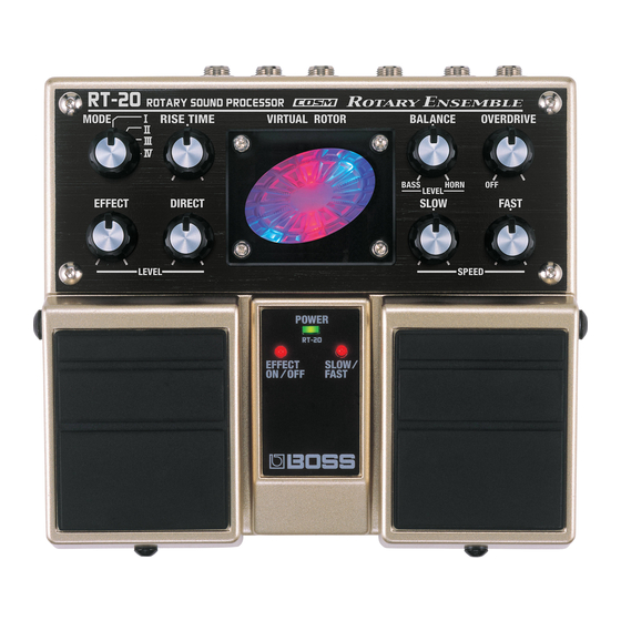
Page 4: Location Of Controls
Dec. 2005 RT-20 Location of Controls fig.panel... -
Page 5: Location Of Controls Parts List
Dec. 2005 RT-20 Location of Controls Parts List [PART] PART CODE PART NAME DESCRIPTION Q’TY G2357116R0 PEDAL PLATE 62X53 G2217749R0 LED PANEL G2217192R0 PANEL 75D522N0R0 MINIMUM VR KNOB G2567163R0 LED COVER G2147880R0 LED LENS G2217191R0 REAR PANEL F3449415 ADAPTOR JACK KM02009AB F3159104 SWITCH... -
Page 6: Exploded View (1)
Dec. 2005 RT-20 Exploded View (1) fig.bunkai1 RIGHT SIDE LEFT SIDE Exploded View (1) Parts List [PART] PART CODE PART NAME DESCRIPTION Q’TY 75E202T000 CASE G2357111R0 CUSHION R H5029851 PEDAL SHAFT 22157702R0 PEDAL GUIDE BUSH 22177109R0 COIL SPRING G2357116R0 PEDAL PLATE 62X53 G2357115 PEDAL FOOT... -
Page 7: Exploded View (2)
Dec. 2005 RT-20 Exploded View (2) fig.bunkai2 Exploded View (2) Parts List [PART] PART CODE PART NAME DESCRIPTION Q’TY G2147880R0 LED LENS 75D522N0R0 MINIMUM VR KNOB G2217192R0 PANEL G2217749R0 LED PANEL G2567163R0 LED COVER [SCREW] PART CODE PART NAME DESCRIPTION Q’TY H5029855 SCREW M4X8... -
Page 8: Exploded View (3)
Dec. 2005 RT-20 Exploded View (3) fig.bunkai3-e Refer to Exploded View (4). Enlargement Enlargement Exploded View (3) Parts List [PART] PART CODE PART NAME DESCRIPTION Q’TY 75D422E000 BOTTOM COVER G2357118 BOTTOM FOOT G2017621R0 BATTERY COVER G2017620 BATTERY CASE G2177308 BATTERY TERMINAL (+) G2177309 BATTERY TERMINAL (-) G2177307... -
Page 9: Exploded View (4)
Dec. 2005 RT-20 Exploded View (4) fig.bunkai4 Exploded View (4) Parts List [PART] PART CODE PART NAME DESCRIPTION Q’TY G225712901 INSULATING SHEET G2217191R0 REAR PANEL G2197127 JACK SPACER 75E203J0R0 JACK BOARD ASSY 75E203P0R0 PANEL BOAD ASSY G2147807 JACK HOLDER [SCREW] PART CODE PART NAME DESCRIPTION... -
Page 10: Parts List
Dec. 2005 RT-20 Parts List fig.part1e Due to one or more of the following reasons, SAFETY PRECAUTIONS: parts with parts code ******** cannot be supplied as service parts. The parts marked have safety-related characteristics. Use only listed parts for replacement. •... - Page 11 Dec. 2005 RT-20 RESISTOR F5419771R0 RESISTOR ARRAY RTA03-4D(0603) 10R RA5, RA4 02124645 MTL.FILM RESISTOR RR0816R-473-D R42, R46 01905001 MTL.FILM RESISTOR RR0816P-103-D R9, R16, R24, R37, R60, R67 F5399950 CHIP RESISTOR(1/2W) R-33 1/2W R33, R57 F2569127 POLY SWITCH MINISMDC075 F5419726 RESISTOR ARRAY CRN34473J RA1, RA2, RA3 F5399158...
- Page 12 Dec. 2005 RT-20 SCREWS H5019110 SCREW M3X6 PAN TAPTITE FEZC H5019115 SCREW M3X8 PAN TAPPING-2 FEBZC H5029852 SCREW 4M3 FEBZC HEXAGON SOCKET BUTTON HEAD H5029901R0 SCREW M3X10 HEXAGON SOCKET (FE/NI) H5029855 SCREW M4X8 HEXAGON BUTTON HEAD NI H5039413 NYLON WASHER BLACK M4.1X7.5X0.5 H5039414...
-
Page 13: Checking The Version Number
Dec. 2005 RT-20 Checking the Version Skipping Number If you set the MODE knob previously as follows before entering the Test Mode, you can specify the start point of the Test Mode. Enter Test Mode and execute “1. CPU, DSP Check” and “2. Version Check” MODE knob I: from 1. - Page 14 Dec. 2005 RT-20 3. Knobs Check Other knobs When rotating the [EFFECT] knob clockwise fully from the MIN position, Press the right pedal to start the Knobs Check. confirm the display of the Virtual Rotor Display changes. And when fig.03-VR-panel rotating it fully to the MAX position, confirm the display of the Virtual Rotor Display changes again.
- Page 15 Dec. 2005 RT-20 5. Expression Pedal Check 6. Analog Bypass Waveform Check Press the right pedal to start the Expression Pedal Check. Press the right pedal to start the Analog Bypass Waveform Check. fig.05-EXP-panel fig.06-ANABYP-panel Connect an EV-5 to the SPEED (EXP PEDAL) jack. Connect an oscilloscope to OUTPUT A (MONO) and OUTPUT B.
- Page 16 Dec. 2005 RT-20 Confirm the output waveform will be like the following picture. 7. Analog Bypass Route FET Switch fig.06-ANABYP-3_70(200 mV/DIV, 1 ms/DIV) Check Press the right pedal to start the Analog Bypass Route FET Switch Check. fig.07-ANASW-panel Confirm the output wave disappears and the following picture appears. fig.07-ANASW-1_70(200 mV/DIV, 1 ms/DIV) 200mV/DIV, 1ms/DIV <<...
- Page 17 Dec. 2005 RT-20 Confirm the output waveform will be like the following picture. 9. DSP Through (Output) Waveform fig.08-DA-2_70(200 mV/DIV, 1 ms/DIV) Check Press the right pedal to start the DSP Though (Output) Waveform Check. fig.09-DSPTHOUT-panel Connect an oscilloscope to OUTPUT A (MONO). Connect an oscillator to INPUT A (MONO) and INPUT B, and input 200mV/DIV, 1ms/DIV rectangular waves of 200 Hz/500 mV p-p.
- Page 18 Dec. 2005 RT-20 11. DSP Route FET Switch Working Check 13. DSP Through Route Residual Noise Check Press the right pedal to start the DSP Route FET Switch Working Check. Press the right pedal to start the DSP Through Route Residual Noise fig.11-DSPSW-panel Check.
- Page 19 Dec. 2005 RT-20...
-
Page 20: Block Diagram
Dec. 2005 RT-20 Block Diagram fig.block@L... - Page 21 Dec. 2005 RT-20 Circuit Board (JACK BOARD) fig.board-jack@L...
-
Page 22: Circuit Board (Jack Board)
Dec. 2005 RT-20 Circuit Board (PANEL BOARD) fig.board-PANEL@L... -
Page 23: Circuit Board (Panel Board)
Dec. 2005 RT-20 Circuit Diagram (JACK BOARD) fig.diagram-jack@L INPUT A D A 1 4 7 k OUTPUT A (MONO) 1SS302 4 7 k (MONO) R 1 1 J K 1 1 0 k 0.0022 J K 2 HTJ-064-12DS 1 0 k 0.1(Film) 100p 1 0 /16... -
Page 24: Circuit Diagram (Jack Board)
Dec. 2005 RT-20 Circuit Diagram (PANEL BOARD) fig.diagram-panel@L 3. 3 V C C _ W AVE 3. 3 3. 3 3. 3 R 1 52 R 1 48 C 1 21 C123 EFFECT SLOW/FAST N I U 47/16 47/16 ON/OFF N I U R 1 45 R 1 46... - Page 25 Dec. 2005 RT-20 MEMO...
- Page 26 Dec. 2005 RT-20 MEMO...
Need help?
Do you have a question about the BOSS RT-20 and is the answer not in the manual?
Questions and answers