Advertisement
Table of Contents
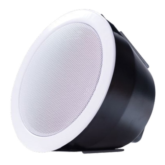
CEILING LOUDSPEAKER
RLS5FTS/EN
Budget ceiling speaker as one-piece version and metal housing.
The mounting is via fast spring clip.
EN54-24:2008
0359-CPR-00279
TYPE A
Standard
Electrical
Rated power, Watts
Tappings 100 volt line, Watts
Transformer Impedance, Ohms 100V
Tappings 70.7 volt line, Watts
Driver impedance, Ohms
Effective Frequency Range, Hz (BSEN60268-5)
S.P.L. @ 4m, 1watt, dB,1/3 Octave, 1KHz
S.P.L. @ 1m, 1watt, dB, Test Signal Bandwidth 100Hz-10kHz
S.P.L. @ 4m, Full power, dB, 1/3 Octave 1KHz
S.P.L. @ 1m, Full power, Test Signal Bandwidth 100Hz-10kHz
Environmental
IP Rating
Min/Max amb temp
Relative Humidity
Mechanical
Dimensions DxT, mm
Net weight, kg
Colour (Unless Specified)
Material
Mounting
Cut-out, mm
Safety
ATEÏS Europe B.V.
Celsiusstraat 1, 2652 XN Lansingerland, Netherlands
Phone +31 (0)10 208 86 90, www.ateis-europe.com, info@ateis-europe.com
RLS5FTSEN_datasheet_AE_en_vn1.0_web
Compliant to EN54-24
Compliant to BS 5839:8
6
6/3/1.5
1.67k/3.33k/6.67k
3/1.5/0.75
4
230-15,000
77
93
85
101
21
-10°C to 55°C
≤95%
Ø186x146
1.02
White RAL9016
Metal
Fast spring clip
Ø162
Ceramic Block
Thermal Fuse
Page 1/2
Advertisement
Table of Contents

Related Manuals for Penton ATEIS RLS5FTS/EN


Summary of Contents for Penton ATEIS RLS5FTS/EN
- Page 1 CEILING LOUDSPEAKER RLS5FTS/EN Budget ceiling speaker as one-piece version and metal housing. The mounting is via fast spring clip. EN54-24:2008 0359-CPR-00279 TYPE A Standard Compliant to EN54-24 Compliant to BS 5839:8 Electrical Rated power, Watts Tappings 100 volt line, Watts 6/3/1.5 Transformer Impedance, Ohms 100V 1.67k/3.33k/6.67k...
- Page 2 INSTALLATION GUIDE RLS5FTS/EN EN54-24:2008 0359-CPR-00279 TYPE A With Transformer: 100V/70V line 1. Loudspeaker enclosure White wire plus tapping Black 2. Reference axis 100V 1.5W 3. Reference plane 4. Horizontal plane 0.75W 1.5W IMP (Ω) 6.67k 3.33k 1.67k 1) Connect the terminal to the speaker circuit. To 2) Attach the junction box with the wing nut 3) Loosen the locking nut “C”...
Need help?
Do you have a question about the ATEIS RLS5FTS/EN and is the answer not in the manual?
Questions and answers