3Com IntelliJack NJ200 User Manual
3com intellijack nj200: user guide
Hide thumbs
Also See for IntelliJack NJ200:
- Software manual (8 pages) ,
- Supplementary manual (14 pages) ,
- Datasheet (4 pages)

Related Manuals for 3Com IntelliJack NJ200


Summary of Contents for 3Com IntelliJack NJ200
-
Page 1: User Guide
User Guide 3Com Network Jack Model NJ200 http://www.3com.com/ http://www.3com.com/productreg Published September 2002 User guide version 1.0... - Page 2 U.S.A. Copyright © 2002 3Com Corporation. All rights reserved. No part of this documentation may be reproduced in any form or by any means or used to make any derivative work (such as translation, transformation, or adaptation) without written permission from 3Com Corporation.
-
Page 3: Table Of Contents
Support from 3Com ........ -
Page 5: Installing The Nj200 Network Jack
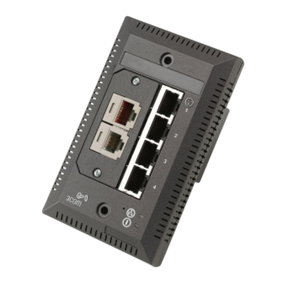
NSTALLING THE The 3Com NJ200 Network Jack is a 4-port, managed Ethernet switch that fits into any standard electrical wall outlet or data port opening. It brings switching capabilities to any single port on an Ethernet network by allowing you to connect up to four networking devices, such as computer, printers, and Voice Over IP (VoIP) telephones to the network via one Ethernet port. -
Page 6: About The Network Jack
PBX telephone. The adapter plates are available from 3Com. However, you must purchase the connectors from the manufacturer. See “Installing the Adapter Plate and Pass-Through Ports” on page 8 for more information. -
Page 7: Before You Begin
The following diagram shows the back view of the Network Jack: Before You Begin Before you begin installation, register your product at: www.3com.com/productreg. The Network Jack is available in single- and 20-packs. Before you begin the installation, make sure you have the following items, which are included with the Network Jack: •... -
Page 8: Obtaining Optional Components
• Adapter plates for installing connectors to use as pass-through ports. The NOTE: The connectors for the adapter plates must be purchased from the manufacturer. For a list of supported connectors, go to www.3com.com/. • Adapter plate screws (2) for mounting the adapter plate to the Network Jack. -
Page 9: Installing The Network Jack
• Over the network via an integrated switch that supports Power Over Ethernet. • Over the network via a multi-port Ethernet power supply. • Over the network via a single-port Ethernet power supply. • Locally via a 3Com local power supply. Installing the Network Jack... - Page 10 NOTE: For a list of power supplies that support the Network Jack, go to www.3com.com/. CAUTION: Use only a power supply that is provided or approved by 3Com for use with this Network Jack. Failure to do so may result in damage to the Network Jack, or may result in a hazardous situation or personal injury.
- Page 11 Using the 3Com Local Power Supply To use the local power supply, make sure you have an electrical outlet near the site where the Network Jack will be installed. First plug the power cord into the Network Jack, then plug it into the electrical socket. See page 12 for more details.
- Page 12 20-pack). For a list of connectors that are supported with the Network Jack adapter plates, go to www.3com.com. NOTE: If you are not planning on installing the adapter plate and pass-through ports, skip this section. Go to “Planning the Installation” on page 9 to begin the installation.
-
Page 13: Planning The Installation
3 Terminate the end of the network cable(s) with the connector(s) you purchased separately. Refer to the connector manufacturer’s instructions for terminating the cable. Be sure to test end-to-end system functionality and verify that it is working. 4 Snap the connector(s) into the appropriate adapter plate. Each adapter plate is labeled with the name of a connector’s manufacturer. - Page 14 1: I NJ200 N HAPTER NSTALLING THE Setting up the Network The network cabling at your site (from the wiring closet to the wall or cubicle Cabling at Your Site opening) may already be installed. If it is not, install the cabling following these general guidelines.
- Page 15 Mounting the Network After connecting the Network Jack to the network, use the two provided screws Jack to mount the Network Jack in any standard NEMA-WD6 cubicle opening or wall outlet. If the cubicle or wall opening has a depth of fewer than 1.5 inches, does not support the NEMA-WD6 standard, or does not have pre-drilled screw holes, mount the Network Jack using the extension ring, as shown below.
- Page 16 4 Secure the local power supply and cable to the wall. 5 Plug the local power supply into the power source. WARNING: Use the local power supply available from 3Com. Failure to do so may result in damage to the Network Jack, or may result in a hazardous situation.
-
Page 17: Checking The Leds
Connecting Devices to After the Network Jack is installed and mounted, connect your networking devices the Network Jack (such as computers, printers, etc.) to any of the four switched ports on the front of the Network Jack. If you installed the adapter plate with pass-through ports, connect the appropriate device(s) to the port(s). - Page 18 1: I NJ200 N HAPTER NSTALLING THE ETWORK...
-
Page 19: Configuration Managers
Windows 98 are not recommended operating systems for use with management platforms. In most cases, the Configuration Manager software will work with Windows 95, 98, or XP. However, please check 3Com’s web site for additional information regarding XP support) Run the following steps to install the Configuration Manager software: Windows NT computer. - Page 20 2: I HAPTER NSTALLING THE ONFIGURATION ANAGERS 3 Click Next to continue. 4 Carefully read the license agreement. If you agree, click “Yes, I accept” and Next to continue. 5 Enter your user and organization names and click Next.
- Page 21 Installing the Local and Central Configuration Managers 6 The program files will be installed in the directory C:\Program Files\3Com\Network Jack. If you want to change the location of the installation, click Change. Otherwise click Next to accept the default location and continue.
- Page 22 2: I HAPTER NSTALLING THE ONFIGURATION ANAGERS 8 Review the settings you selected and click the Install button. 9 When the installation has completed, click the Finish button to close the installation utility.
- Page 23 Local Configuration Manager and one for the Central Configuration Manager. You can also launch the programs from a program group you can access from the Start menu. The program group folder is labeled 3Com Network Jack and can be found under the Programs menu.
- Page 24 2: I HAPTER NSTALLING THE ONFIGURATION ANAGERS...
-
Page 25: Sing The Local Configuration Manager
Initializing the NJ200 Network Jack 1 The first step is to connect your computer to the NJ200 that you are installing. 2 Click on the desktop shortcut icon labeled NJ200 Local Config Mgr to start the 3 The MAC address and default IP address of the currently connected NJ200 will 4 Make sure the General tab is selected. -
Page 26: Setting Advanced Options
3: U HAPTER SING THE OCAL 6 Enter a Group Name for this Network Jack. This can be any name you wish. With the Central Configuration Manager, you can perform management tasks on all Network Jacks with the same group designation. 7 Select the method the NJ200 should use to obtain an IP address. - Page 27 Make sure you remember the new password you set. If you forget the new password, you will not be able to perform any other configuration tasks unless you send the device back to 3Com. Setting Advanced Options...
- Page 28 3: U HAPTER SING THE OCAL ONFIGURATION ANAGER...
-
Page 29: Sing The Central Configuration Manager
You should use the Local Configuration Manager to initialize each of the NJ200 Network Jacks installed on your network. Once you have completed that step, you can manage all of them with the Central Configuration Manager. Install this program on any computer on your network you want to use as a central management console (See chapter 2, “Installing the Configuration Managers”... - Page 30 4: U HAPTER SING THE ENTRAL 2 Select Discovery from the Devices menu. The following window will appear: NOTE: The default subnets are the ones your machine is connected to. 3 You can discover new devices based on a specific subnet or on a specific range of IP addresses.
-
Page 31: Viewing Device Properties
4 If the box next to “Delete all devices in the existing list” is checked, the discovery process will replace all of the devices in your current database with the new devices it discovers. If unchecked, the discovery process will add newly discovered devices to the current database. - Page 32 4: U HAPTER SING THE ENTRAL at one time, see “Changing Device Configuration” on page 31. To get more detailed information about a device, you should check its properties: 1 Select a Network Jack from the devices list. 2 Select Property from the Devices menu or from the toolbar. You can also open this window by right-clicking your mouse and selecting Property.
- Page 33 7 Click on the Hardware Settings tab to view status information about the switch. Several fields in this window can be edited, a few cannot. You can change the values of the fields with drop-down lists: Priority Schedule Policy, LAN Port Egress Mode, LAN Port Ingress Mode, Max Frame Size, Counter Mode, and Power Forwarding.
- Page 34 4: U HAPTER SING THE ENTRAL ONFIGURATION ANAGER 9 Click on the Statistics tab. From this view you can see statistics about the number of good or bad packets each port has received and transmitted, based on how you have configured the Counter Mode setting (see step 8 on page 33).
-
Page 35: Changing Device Configuration
10 Click on the SNMP Settings tab to see the following window: 11 You can view and edit the SNMP Common Settings and Trap Settings for this particular NJ200. 12 Click Apply to save any changes you make and a configuration summary dialog box will appear. - Page 36 4: U HAPTER SING THE ENTRAL 2 Select Configuration from the Devices menu or the toolbar or right click on a device and select Configuration from the pop-up menu. NOTE: To make configuration changes to a Network Jack from the Central Configuration Manager, the NJ200 must already be discovered and part of the device database, and you must be able to communicate with the device from your workstation.
- Page 37 8 By default, the Central Configuration Manager will display a count of good transmissions in the Property window. If you would rather track errors and collisions, select that option in the Counter Mode setting. 9 Click the Priority tab along the top of the Device Configuration window to view these settings: 10 From this screen you can change the Look Up Scheme and Default Priority Level of each port on the NJ200 and the Priority Scheduling Policy of the Network Jack...
- Page 38 4: U HAPTER SING THE ENTRAL 11 Click the VLAN tab to configure your Network Jack for use in a virtual LAN. 12 From this window you can associate any of the four ports with any other ports on this Network Jack to form a VLAN group. You can specify the tag schemes for the VLAN you create.
- Page 39 Changing Device Configuration 13 Select the Security tab to set the security options of the NJ200 Network Jack. 14 You can change the device password (the default password is “password”), and adjust the SNMP Set permissions and Community Strings.
- Page 40 4: U HAPTER SING THE ENTRAL ONFIGURATION ANAGER 15 Click the SNMP Traps tab to change the trap settings of the NJ200. 16 From this window you can enable or disable the device’s Cold Start, Link Down, Link Up, and Authorization Fail traps to be sent to your SNMP console.
- Page 41 17 Select the Advanced tab for this window: 18 You can change the Max Frame Size and Power Forward settings by selecting an option from the drop-down list. 19 From this window, you can see another set of tabs, one for each port on the Network Jack.
- Page 42 4: U HAPTER SING THE ENTRAL Port Setting State Link Flow Control MDI[X] Multicast Limit Priority Lookup Port Priority VLAN ID Port based VLAN The values that remain unchanged when you click Restore Factory Default Settings are: • Group Name •...
-
Page 43: Finding Computers Connected To Nj200 Devices
22 If you click Configuration Summary, you will see a summary of all the changes you have made. Enter your password and click Start. As the Network Jacks are configured, their status will be updated in the Status column. NOTE: If a NJ200 Network Jack that was once discovered by the Central Configuration Manager is no longer connected to your network or if you just want to remove a device from the current database, you can select Delete Device from the Devices menu. -
Page 44: Upgrading The Nj200 Firmware
4: U HAPTER SING THE ENTRAL Upgrading the NJ200 You can upgrade the firmware on your NJ200s over the network from the Central Firmware Configuration Manager. To do so, follow these steps: 1 Select one or more Network Jacks you want to upgrade. You can select groups of Network Jacks using one of the grouping options available to you in the drop-down list at the top left corner of the main window. - Page 45 5 Select the time to perform the upgrade. You can either send the update file immediately or select a specific time and date to send the file. You may, for example, want to perform an upgrade during off hours such as a weekend. 6 Click Next and a window like this will appear: 7 Review the list of Network Jacks you want to upgrade.
- Page 46 4: U HAPTER SING THE ENTRAL ONFIGURATION ANAGER 8 Type your password in the Password field, then click Finish. The Upgrade Progress dialog box will appear.
- Page 47 Upgrading the NJ200 Firmware Viewing Log Files The Central Configuration Manager creates a log file with details of the firmware upgrade operation. This file is in the Central Configurator\Log subdirectory under the directory where you installed the Network Jack configuration software. You can also view a history of firmware upgrades by selecting Log History from the View menu.
-
Page 48: Viewing And Canceling Scheduled Firmware Upgrades
4: U HAPTER SING THE ENTRAL Viewing and Canceling You can select a time and date to send an upgraded firmware image to the Scheduled Firmware Network Jacks in your network. To view and make changes to the firmware Upgrades upgrades you have scheduled, follow these steps: 1 Select Scheduled Upgrade from the View menu. -
Page 49: Troubleshooting The Nj200
Troubleshooting the NJ200 If you encounter problems with the Network Jack: Verify the Network Jack is receiving power by viewing the Power LED (it should be on). If the Power LED is not on, make sure the: Power Over Ethernet dip switches are set correctly (for either Capacitive Power Discovery Process 24V or 48V or IEEE 802.3af), if your network supports Power Over Ethernet. - Page 50 Troubleshooting the NJ200 Event/Message Green LEDs on Ports 1-4 are not on Amber LED on Port 1 is not lit Authentication Failure Timeout Attributes Error General Error Description Solution Network device has no Make sure the cable is properly connection to Network Jack connected to the network device.
-
Page 51: Technical Support
3Com recommends that you access the 3Com Corporation World Wide Web site. Online Technical Services Register for support at support.3com.com/registration/frontpg.pl 3Com offers worldwide product support 24 hours a day, 7 days a week, through the following online systems: World Wide Web site 3Com Knowledgebase Web Services... -
Page 52: 3Com Connection Assistant
Support from Your Network Supplier If you require additional assistance, consult your network supplier. Many suppliers are authorized 3Com service partners who are qualified to provide a variety of services, including network planning, installation, hardware maintenance, application training, and support services. -
Page 53: Support From 3Com
Support from 3Com If you are unable to obtain assistance from the 3Com online technical resources or from your network supplier, 3Com offers technical telephone support services. To find out more about your support options, go to the Web site associated with your region of the world shown below. - Page 54 Technical Support...
-
Page 55: Product Specifications
Product Specifications Hardware Power consumption Network Interface 10 Mbps Ethernet 10BASE-T 100 Mbps Ethernet 100BASE-TX Performance Auto-negotiation <5 watts without power forwarding Maximum 13 watts with power forwarding (depending on the device drawing power) Ethernet IEEE 802.3 industry standard for a 10 Mbps baseband CSMA/CD local area network Ethernet IEEE 802.3u industry standard for a 100 Mbps baseband CSMA/CD local area network... - Page 56 Product Specifications Environment Operating temperature Storage temperature Operating humidity Storage humidity Operating Altitude Storage Altitude Standards Conformance IEEE 802.3 10BASE-T, 100BASE-TX and auto-negotiation Power Over Ethernet (Capacitive Power Discovery Process and IEEE 802.3af) Power forwarding (IEEE 802.3; 6 watts, 48 volts) Features Power Over Ethernet Local power supply...
- Page 57 Changes or modifications not expressly approved by 3Com could void the user’s authority to operate this equipment. (IC)
Need help?
Do you have a question about the IntelliJack NJ200 and is the answer not in the manual?
Questions and answers