Table of Contents
Advertisement
Quick Links
Advertisement
Table of Contents

Related Manuals for IFM DU110S


Summary of Contents for IFM DU110S
- Page 1 Original Installation Instructions Safety Underspeed Monitor DU110S...
-
Page 2: Table Of Contents
Contents 1 Preliminary note ���������������������������������������������������������������������������������������������������4 1�1 Symbols used ������������������������������������������������������������������������������������������������4 1�2 Warnings used �����������������������������������������������������������������������������������������������5 2 Safety instructions �����������������������������������������������������������������������������������������������5 2�1 General requirements on the safety-related functions �����������������������������������6 3 Functions and features ����������������������������������������������������������������������������������������7 3�1 General function description ��������������������������������������������������������������������������7 3�2 Safe state of the output relays (failsafe state) �����������������������������������������������7 3�3 Switching function "underspeed"... - Page 3 8 Technical data ����������������������������������������������������������������������������������������������������26 9 Maintenance, repair and disposal ����������������������������������������������������������������������28 10 Approvals/standards ����������������������������������������������������������������������������������������28 11 Terms and abbreviations ����������������������������������������������������������������������������������29 This document is the original instructions�...
-
Page 4: Preliminary Note
Read the instructions before use to familiarise yourself with operating conditions, installation and operation�Adhere to the safety instructions� Instructions, technical data, approvals, accessories and further information at www�ifm�com� 1.1 Symbols used ► Instruction >... -
Page 5: 1�2 Warnings Used
1.2 Warnings used WARNING! Warning of serious personal injury� Death or serious irreversible injuries may result� CAUTION! Warning of personal injury� Slight reversible injuries may result� ATTENTION! Warning of damage to property� 2 Safety instructions • Follow the operating instructions� •... -
Page 6: 2�1 General Requirements On The Safety-Related Functions
• Use the unit only in specified environmental conditions (→ 8 Technical data)� In case of special operating conditions please contact the manufacturer� • Use only as described below (→ 3 Functions and features)� 2.1 General requirements on the safety-related functions The device complies with the functional and organisational requirements of EN ISO 13849-1 Performance-Level "e"... -
Page 7: Functions And Features
3 Functions and features 3.1 General function description The device is a two-channel pulse evaluation system for safe underspeed detection� To do so, it receives the pulse sequences from the pulse pick-ups connected to the inputs� The device calculates the resulting frequency� By continuously comparing the input frequency (actual value) and the switch point (target value) the device promptly detects underspeed of the set switch point�... -
Page 8: 3�3 Switching Function "Underspeed
3.3 Switching function "underspeed" The output relays de-energise when underspeed occurs (frequency FuH has been reached)� The relays energise again when the input frequency exceeds the set switch point Fu� f in Safety output Switching characteristics of the current paths (safety-related outputs) Frequency underspeed (= set switch point) Fuh: Frequency underspeed –... -
Page 9: 3�6 Start-Up Delay
3.6 Start-up delay To suppress unintended switch-off of the current paths during the start-up of the machine the device has a fixed start-up delay of 10 seconds� VORSICHT! Personal injury may result� During these 10 seconds the protective function is temporarily suspended�... -
Page 10: 3�7 Fault Output (Y7)
3.7 Fault output (Y7) The transistor output "Fault" (Y7) opens when an internal or external error occurs� The error message is reset by interrupting the voltage supply� 3.8 Underspeed output (Y8) The underspeed output (Y8) is "HIGH" when the current paths are closed and "LOW"... -
Page 11: Installation
4 Installation 4.1 Mechanical installation of the device ► Mount the device on a 35 mm DIN rail in a housing protected against dust and humidity (min� IP 54)� Leave enough space between the device and the top and bottom of the housing to enable air circulation and to avoid excessive heating�... -
Page 12: Electrical Connection
5 Electrical connection 5.1 Terminals Terminals Plug Terminal Connection Supply voltage (+ 24 V DC) protected by a resettable fuse short-circuit proof, not monitored Sensor 1 supply (+ 24 V DC) Sensor 1 GND (0 V DC) Sensor 1 input... - Page 13 Plug Terminal Connection Supply voltage (GND) directly connected to the device ground Sensor 2 supply (+ 24 V DC) Sensor 2 GND (0 V DC) Sensor 2 input Current path 1A (relay contacts) (not connected) (not connected) Current path 1B (relay contacts) Deactivation of the monitoring function (P) (→...
-
Page 14: 5�2 Automatic/Manual Mode Selection
5.2 Automatic/manual mode selection If underspeed is detected, the current paths open and the drive is switched off� The manual operation can prevent the current paths closing automatically as soon as the input frequency exceeds the Fu value again� The operating mode is selected via the circuitry of two input terminals Y5 and Y6� 5.2.1 Automatic operation In this operating mode the device compares the input frequency with the set switch point�... - Page 15 Automatic operation (circuitry of the inputs Y5 and Y6) The automatic operation mode is implemented by connecting input Y5 to Y1 (pulsed test signal) and input Y6 to + 24 V DC� If the device detects an error, it returns to the safe state (→ 3.2 Safe state of the output relays (failsafe state))�...
-
Page 16: 5�2�2 Manual Operation
5.2.2 Manual operation In this operating mode, the outputs of the device are only switched if the input frequency is above the switch point Fu and after the restart signal has been sent to the device via an external restart command element� When the underspeed has been detected, the current paths are open�... - Page 17 The restart command element must be installed outside the hazardous area in a position where the hazardous area and the entire work area concerned are clearly visible� The device may also be installed within the hazardous area since handling is not required during operation� When the device is waiting for the restart command, the yellow LED [ENA] flashes�...
-
Page 18: 5�3 Enable Inputs
5.3 Enable inputs If several devices with different switch points are used for underspeed monitoring of a drive, devices whose switch point value is not relevant can be "switched off" by means of the two enable inputs� The monitoring function of these devices is then deactivated; the current paths are closed�... -
Page 19: Indicators And Operating Elements
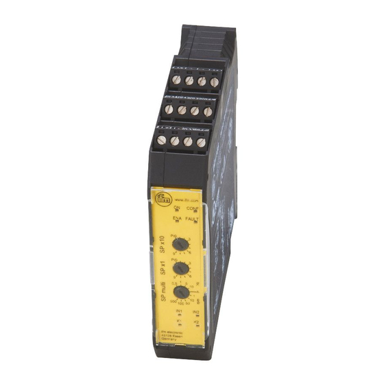
6 Indicators and operating elements CONF FAULT 1: LEDs 2: Switches (270° potentiometer, 10 positions, locking) 6.1 LEDs Colour Description Green Power ON when device is switched on� CONF Blue Configuration ON when device in configuration mode� Flashing when switches are in P position� Yellow Enable ON when the enable inputs are logically on�... - Page 20 Colour Description FAULT Error ON when an internal fault was detected� Flashing when an external fault was detected� Manual/automatic configuration error Switches in incorrect position (frequency selectors) Feedback circuit error Sensor error (function or wiring) Current > 500 mA on output S33, S44, Y1, Y7 or Y8 Flashing alternately with ENA, CONF, IN1/2 and K1/2 when a sensor is not connected�...
-
Page 21: Set
7 Set-up When the device is switched on for the first time, it is necessary to configure the underspeed frequency (Fu) using the three switches� The 3 switches allow the user to enter the value of the desired preset frequency� •... -
Page 22: 7�2 Setting The Switch Point
7.2 Setting the switch point Step 1: ► Switch off power supply of the device� ► Set the 3 switches to configuration position P or P/0 (→ 7.1)� ► Switch on power supply of the device� > Device is in the configuration mode� >... -
Page 23: 7�3 Examples Of Switch Point Settings
7.3 Examples of switch point settings 0,5 1 0,5 1 520 Hz 6700 rpm The unit rpm is only applicable when 1 cam/revolution is present� For several cams: Multiply the required switch point by the number of cams� Example Required switch point: 1000 rpm Number of cams: Setting value:... -
Page 24: 7�5 Notes On The Positioning Of The Sensors / Damping Elements
7.5 Notes on the positioning of the sensors / damping ele- ments The device checks whether the frequencies at both inputs are identical (within the corresponding tolerances)� If the direction of movement remains unchanged, the sensors can be positioned anywhere within the damping zone� Example: 1 direction of movement The input signals may look like this: same frequency, time lag... - Page 25 In case of repeated movements within the indicated angle, the two sensors will detect different frequencies and the device will signal an error� The error will be signalled by the LEDs FAULT, IN1 and IN2 flashing four times� no signal at IN1, error message at Y7 The problem can be solved by positioning the sensors / damping elements differently, so that the pulses are detected correctly by both sensors�...
-
Page 26: Technical Data
8 Technical data DU110S Safety underspeed Monitor Evaluation systems 1: screw terminals 2: Rotary switch 3: Mounting on DIN rail Product characteristics Safe speed monitor for underspeed detection Evaluation system for safe speed monitoring for 2 pnp switching sensors Diagnostic and fault output Adjustable frequency range 0.5...990 Hz / speed range 1...49500 rpm... - Page 27 = input frequency (sensors) RoHS compliant Pack quantity [piece] ifm electronic gmbh • Friedrichstraße 1 • 45128 Essen — We reserve the right to make technical alterations without prior notice. — GB — DU110S-00 — 12.08.2020 Seite 2 von 2...
-
Page 28: Maintenance, Repair And Disposal
• EN ISO 13849-1: 2008 Safety of machines - safety-related parts of control systems • IEC 61508: 2011 Functional safety of electrical/electronic/programmable electronic safety-related systems • EN 60204-1: (1997) (where applicable) Electrical equipment of machines • UL 508� The EU declaration of conformity and approvals can be found at: www�ifm�com... -
Page 29: Terms And Abbreviations
11 Terms and abbreviations Cat� Classification of the safety-related parts of a controller as regards their resistance to failures� Common Cause Failure Diagnostic Coverage MTTF Mean Time to Failure MTTF Mean Time To Dangerous Failure Probability of Failure per Hour Probability of Dangerous Failure per Hour Performance Level PL to EN ISO 13849-1...
Need help?
Do you have a question about the DU110S and is the answer not in the manual?
Questions and answers