
Related Manuals for IFM G2001S


Summary of Contents for IFM G2001S
- Page 1 Original operating instructions Safety relay with relay outputs and muting function G2001S...
-
Page 2: Table Of Contents
Contents 1 Preliminary note ���������������������������������������������������������������������������������������������������4 1�1 Symbols used ������������������������������������������������������������������������������������������������4 1�2 Warning signs used ���������������������������������������������������������������������������������������4 2 Safety instructions �����������������������������������������������������������������������������������������������4 3 Items supplied������������������������������������������������������������������������������������������������������5 4 Functions and features ����������������������������������������������������������������������������������������6 4�1 Requirements for the hardware configuration �����������������������������������������������6 4�1�1 Product-independent requirements ������������������������������������������������������6 4�1�2 Product-dependent requirements ���������������������������������������������������������6 5 Structure and operating principle �������������������������������������������������������������������������7 5�1 Connections and indicators ���������������������������������������������������������������������������7 5�1�1 Connections ������������������������������������������������������������������������������������������7... - Page 3 8�5�2 Override with command pulse ������������������������������������������������������������22 9 Scale drawing ����������������������������������������������������������������������������������������������������22 10 Technical data ��������������������������������������������������������������������������������������������������23 11 Fault diagnoses �����������������������������������������������������������������������������������������������24 12 Maintenance, repair and disposal ��������������������������������������������������������������������25 13 Tests/approvals ������������������������������������������������������������������������������������������������25 14 Terms and abbreviations ����������������������������������������������������������������������������������26...
-
Page 4: Preliminary Note
1 Preliminary note The instructions are part of the unit� They are intended for authorised persons according to the EMC and low voltage directives and safety regulations� The instructions contain information about the correct handling of the product� Read the instructions before use to familiarise yourself with operating conditions, installation and operation�... -
Page 5: Items Supplied
► The safety relay must only be used under the specified operating conditions and in accordance with use as prescribed below� 3 Items supplied • 1 G2001S safety relay • 1 copy of the operating instructions safety relay, reference 704576� If one of the above-mentioned components is missing or damaged, please contact... -
Page 6: Functions And Features
4 Functions and features The G2001S safety relay is a redundant system and suited for use as muting relay in conjunction with 2 muting sensors� ifm electronic gmbh assumes no liability for the use of units made by external manufacturers�... -
Page 7: Structure And Operating Principle
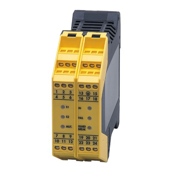
5 Structure and operating principle 5.1 Connections and indicators 16 17 18 FAIL GUARD MUT. BREAK 5.1.1 Connections Muting sensor S1 Supply voltage L- Muting sensor S2 PE (GND) Supply voltage L+ Restart Timeout 1 n� c� Timeout 2 Input OSSD 1 Operating mode MAN/AUTO Input OSSD 2 Override 1... -
Page 8: 5�1�3 Led States
5.1.3 LED states MUT. FAIL GUARD MUT. yellow yellow yellow BREAK Description Switch-on test Object detected No object detected Muting active Override request FAIL GUARD/BREAK FAIL GUARD MUT. green yellow green BREAK Description Switch-on test Protected area interrupted, relay outputs deactivated Protected area clear, relay output deactivated, waiting for restart... -
Page 9: Installation
6 Installation Mount the unit on a DIN rail in a housing protected against dust and humidity (min� IP 54 - degree of soiling 2)� Leave enough space between the unit and the top and bottom of the housing to enable air circulation and to avoid excessive heating�... -
Page 10: 7�2 Automatic Or Manual Operation / Feedback Contacts
After power on or a reset the unit carries out self diagnostic functions� After this self diagnosis the unit is ready for operation� 7.2 Automatic or manual operation / feedback contacts Automatic operation Automatic activation without monitoring� Automatic operation with monitoring of the feedback contacts Release is made when the feedback contacts are closed�... -
Page 11: 7�3 Muting
Manual operation with monitoring of the feedback contacts Activate the relay outputs: The feedback contacts are closed ► Press and release restart (> 100 ms)� Consider the current flowing through the feedback contacts (→ 10 Technical data)� 1: Restart 2: Feedback contacts ►... -
Page 12: 7�4 Timeout
Muting lamp Prerequisite for the muting function is the connection of a muting lamp (0,5���5 W)� Muting activation To start the muting function a high signal (24 V) has to be applied to terminal 11� A continuous signal or a pulse > 1 s can be used� 7.4 Timeout Timeout is a time limit of the muting function�... -
Page 13: 7�5 Override
7.5 Override Do not short-circuit terminals 7 and 8� Override with continuous command ► Use a key-operated switch with spring return� The command pulse must be applied simultaneously to both terminals within 400 ms� 1: Key-operated switch Override with command pulse The command pulse must invert the condition of terminals 7 and 8 within 400 ms�... -
Page 14: 7�7 Output Circuit
7.7 Output circuit Connect the load ► Connect the load to be controlled to the relay outputs 23/24 or 12/22� For the output circuit, the G2001S uses two guided contact safety relays� 3,6 A ► Protect the output contacts with a slow-acting 3,6 A fuse�... -
Page 15: 7�8 Overview
7.8 Overview Automatic operation with monitoring of the feedback contacts and timeout 30 s Sensor 1 0 V DC Sensor 2 Restart 24 V DC Timeout 1 n. c. Timeout 2 Input OSSD 1 MAN/AUTO Input OSSD 2 Override 1 n. - Page 16 Manual operation with monitoring of the feedback contacts and timeout 30 s Sensor 1 0 V DC Sensor 2 Restart 24 V DC Timeout 1 n. c. Timeout 2 Input OSSD 1 MAN/AUTO Input OSSD 2 Override 1 n. c. Override 2 K1/K2 feedback n.
-
Page 17: Operating Modes
8 Operating modes After new installation or change of the operating mode check the function of the entire safety system (safety relay and safety light curtains / light grids)� 8.1 Automatic operation If the safety relay is used in the automatic mode, monitored start is not possible� The safety light curtains / light grids automatically return to operation if the pro- tected area is clear, the relay outputs (OSSDs) are activated�... -
Page 18: 8�3 K1/K2 Feedback Contacts
Check if this function is compatible with the risk analysis of your machine and if additional measures have to be taken� The following components are necessary for the muting function: - G2001S safety relay - safety light curtain / safety light grid - 2 muting sensors - muting lamp (0,5���5 W) -
Page 19: 8�4�1 Alignment Of 2 Muting Sensors
To start the muting function a high signal (24 V) must be applied to terminal 11 (muting activation) for 1 s� Correct alignment of the muting sensors is imperative for the proper func- tion of the safety relay� 8.4.1 Alignment of 2 muting sensors 1: Muting sensor 1 4: Safety light curtain / safety light grid 2: Muting sensor 2... - Page 20 Muting ends after release of the muting sensors Muting sensor 1 Muting sensor 2 Time limit clear Protected area interrupted Muting Timer Muting enable Relay outputs Muting ends after the time limit (timeout 30 s) has elapsed Muting sensor 1 Muting sensor 2 Time limit clear...
-
Page 21: 8�5 Override
8.5 Override Override means suspension of the safety function� It ensures a controlled restart to transport jammed material out of the protected area� WARNING During the whole override function access to the hazardous area is not protected by the safety light curtains / light grids. Death or serious irreversible injuries may result�... -
Page 22: 8�5�2 Override With Command Pulse
8.5.2 Override with command pulse ► Press override button > Bridging the safety light curtains / light grids for max� 15 min� The function can be started again by activating the override button at the following conditions: - max� 30 subsequent override command pulses - max�... -
Page 23: Technical Data
10 Technical data G2001S Safety relay with relay outputs Meets the requirements of: EN ISO 13849-1 (2008) category 4 PL e, SIL 3 (IEC 61508), SIL 3 (IEC 62061) Electrical design relay Output function 2 safety-related normally open contacts (floating contacts, 2 A / 250 V);... -
Page 24: Fault Diagnoses
Fault of the external relay K1/K2 Wrong output configuration Configuration changed without restart ► make a restart Possible overload or wrong connection of the auxiliary output If the fault cannot be eliminated, switch off the entire machine and contact the ifm service hotline�... -
Page 25: Maintenance, Repair And Disposal
• After use dispose of the unit in an environmentally friendly way in accordance with the applicable national regulations� 13 Tests/approvals The G2001S safety relay was tested and certified by TÜV Süd� The safety relay was developed and tested in accordance with, for example, the following direc- tives and standards: •... -
Page 26: Terms And Abbreviations
Probability of (dangerous) (PFH Failure per Hour Performance Level PL to EN ISO 13849-1 Safety Integrity Level SIL 1-4 to IEC 61508 Programmable Logic Controller Technical data and further information at www.ifm.com → Select your country → Data sheet direct:...
Need help?
Do you have a question about the G2001S and is the answer not in the manual?
Questions and answers