
Subscribe to Our Youtube Channel
Related Manuals for Technicolor COM3000


Summary of Contents for Technicolor COM3000
- Page 1 Technicolor COM3000 Integrator’s Manual w w w . t e c h n i c o l o r . c o m / m c s Page 1...
- Page 2 Revision Record Revision Date Revision Editor Revision Description Draft1 2/18 Angelo Peruch draft Draft2 4/25/18 Angelo Peruch Added UL information in Sections 2.1 and 12 Added System lock feature Added QAM20 section Added “disable flooding” in COM400 switch settings 5/14 Angelo Peruch 6/6/18 Doug Strachota...
-
Page 3: Table Of Contents
Contents Definitions ........................... 9 Introduction ..........................12 Intended Usage ..........................12 COM3000 Product Overview ....................13 Additional Features ......................... 15 Compatibility with Previous Hardware ................... 16 Mechanical Overview ........................16 COM400 Chassis ..........................16 COM51 Card ............................ 18 COM51A ............................19 QAM20 ............................ - Page 4 6.4.1 Explanation of Discover Page Fields ..................49 The Basic Channel Tune Screen....................... 51 Advanced Tune ..........................52 6.6.1 Informational Status ........................ 55 Displaying COM3000 Status ......................63 Pairing Info ............................64 TuneAll ............................67 6.10 Help ..............................69 6.11 SysInfo .............................
- Page 5 6.14 EPG ..............................72 6.14.1 Guide.XML Overview ....................... 74 6.14.2 Getting Started with EPG ......................75 6.14.3 EPG for IP Multicast Systems ....................78 6.14.4 EPG Customization and Channel Mapping ................78 6.14.5 EPG Editing ..........................79 6.15 Welcome Screen ..........................80 6.15.1 Welcome Screen Image Creation ....................
- Page 6 Table of Figures 1 - COM3000 ........................14 IGURE 2 COM400 C ......................16 IGURE HASSIS 3 - COM51 C ........................18 IGURE 4 - QAM20 ..........................20 IGURE 5 - COM51 S ....................21 IGURE YSTEM IAGRAM 6 - I QAM20 COM51 ..............
- Page 7 XAMPLE 55 – S EPG I ..................72 IGURE NFORMATION 56 - IPG S ......................74 IGURE ETUP 57 - COM3000 EPG P ....................75 IGURE 58- COM51 EPG L ......................77 IGURE 59 M .XML ....................78 IGURE ULTICAST...
- Page 8 64 - C ............... 82 IGURE ORRECTLY IZED ELCOME CREEN MAGE 65 U COM51 TFTP ..................83 IGURE PLOAD ILE TO 66 - U EPG ..............83 IGURE PLOAD ELCOME CREEN MAGE TO 67 - A PSIP ............. 84 IGURE DDING ELCOME CREEN TO...
-
Page 9: Definitions
A PC on site, connected to the internet running Team Viewer or a similar remote desktop program. PC will need to be on the same IP subnet as the COM3000 system VPN router set up for remote access via a Virtual Private Network ATSC Advanced Television Systems Committee. - Page 10 DIRECTV HD signals are MPEG4 contained in a MPEG2 transport stream. Many residential and some older commercial TVs will only support MPEG2 signals and will require transcription from MPEG4 to MPEG2, or the use of a setback box like the Technicolor DCI401MCS.
- Page 11 This network consists of the dish, LNB and associated equipment necessary to provide Distribution KA/KU band satellite signals to the COM3000. The COM3000 requires a SWiM signal to Network each card proportional to the number of tuners desired. It is assumed that installation technicians have adequate expertise and proper test equipment required to install the distribution system to AT&T / DIRECTV specifications.
-
Page 12: Introduction
COMMERCIAL USE This product is designed to go into areas that are not accessible to the public at large and are not for home use. Technicolor COM3000 Products provide Head-End systems for distribution solutions for the AT&T / DIRECTV Commercial and Lodging and Institutions (L&I) markets w w w . -
Page 13: Com3000 Product Overview
Full 38.8 Mbps QAM capacity o New easy to use setup Configured with 6 COM51 receivers and one QAM20 a COM3000 can tune up to 138 AT&T / DIRECTV channels. ➢ Each COM51 card can receive up to 23 AT&T / DIRECTV channels. -
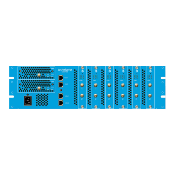
Page 14: Figure 1 - Com3000
COM400 chassis. ➢ The COM51 card includes a built-in web interface and can be configured using a web browser. ➢ To view high definition video from the COM3000 a TV or set top box equipped with decryption technology must be used. -
Page 15: Additional Features
➢ Internal “home screen” channels can be configured to stream static image message screens direct from the COM3000 system. No additional equipment required. ➢ Vidplay utilizes a free program developed by Technicolor that will stream a MPEG2 transport stream file from a connected PC (not provided) to the Technicolor QAM20 modulator for locally originated video programming. -
Page 16: Compatibility With Previous Hardware
Compatibility with Previous Hardware ➢ COM400 chassis will support COM46 cards but not QAM6. ➢ COM51 Cards will work in COM360 Chassis o A COM46 will only show the first 12 QAM carriers on the QAM20. o A COM360 can only stream 1 Gb to a QAM20. Mechanical Overview The following sections contain a brief overview of the devices that you will be interacting with along with the associated hardware. - Page 17 ➢ MTFB (Mean Time Before Failure) >43,800 hours (five years). ➢ Chassis number assigned via dipswitch beneath top cover access panel. ➢ Ventilation flows from front air vents to rear exhaust fans. Maintain adequate space for free air flow through system. ➢...
-
Page 18: Com51 Card
➢ Compatible with legacy COM360 chassis and QAM6 modulators with limitations ➢ Manual software updates via internal TFTP server. ➢ Queries Technicolor update server for software updates at bootup and at daily intervals, downloads and installs software automatically. o Server will instruct COM51 to complete update at a prespecified time in early AM hours. -
Page 19: Com51A
COM51A COM51A is a specially configured COM51 card which works only with the Technicolor NTSC-8 analog modulator. ➢ It will not stream IP video to a QAM or ethernet port. ➢ Only the NTSC-8 will receive video data from a COM51A. -
Page 20: Qam20
QAM20 Figure 4 - QAM20 The QAM20, shown above in Figure 4 is an Edge QAM256 modulator capable of outputting up to 48 QAM carriers. ➢ QAM20 ships from the factory authorized for 16 QAM carriers. The unit is upgradable in 2 QAM increments via optional software license (SWQAM2) to a maximum of 48 QAM output carriers. -
Page 21: Installation Overview
Figure 5 - COM51 System Diagram Pre-Installation The COM3000 System is quite a bit different from the AT&T / DIRECTV set-top box (STB) receiver traditionally used in these installations. The COM3000 does not natively decode any audio or video, instead relying upon other devices in the system to decode and display the MPEG streams it produces. -
Page 22: Required Tools
➢ It is recommended that a TV of the same make and model used at the jobsite be available in the Headend / MDF room for testing. ➢ IPTV installers should have a preconfigured and tested IGMP switch to verify IP outputs from the COM3000. Site Survey Prior to installation, it is recommended that a detailed site survey is conducted. -
Page 23: Distribution Networks
➢ Eliminate possible signal ingress into the RF plant from VHF broadcast signals ➢ Keep the property signal out of the aeronautical frequencies in the 126 – 134 MHz range. The COM3000 can modulate up to three AT&T / DIRECTV high definition programs on one 6MHz QAM carrier. -
Page 24: External Video Sources
➢ Research and familiarize yourself with all required television programming procedures. ➢ Non-compatible TVs can be used with a Pro:Idiom set back box such as the Technicolor DCI401MCS. w w w . t e c h n i c o l o r . c o m / m c s... -
Page 25: Installation Guidelines
➢ It is required that COM51 cards be connected to a DSWiM30 module for full 23 tuner capability. ➢ Connecting a DSWiM output to the COM51 lower RF input support 15 tuners. ➢ The COM3000 system is designed to operate properly in ambient environments of 104 °F (40°C) or less. -
Page 26: Component Assembly
4.12 Component Assembly ➢ Carefully unpack and install the QAM20 and COM51 cards in the COM400 Chassis as shown below in Figure 6. Be sure to line up the cards with the guides in the chassis. ➢ After inserting the COM51 card, finger tighten the two thumb screws to secure the card in the chassis. -
Page 27: Setting Up Multiple Chassis
4.13 Setting up Multiple Chassis For multi-chassis installations each chassis will need to be assigned a unique chassis ID. ➢ The COM400 chassis has a default setting as chassis one. ➢ Chassis identification is configured via a dipswitch on the backplane circuit board. ➢... - Page 28 The table below details chassis dipswitch settings and the corresponding IP address. Chassis ID Switch1 Switch 2 Switch 3 Switch4 Default IP DOWN DOWN DOWN 192.168.3.18 DOWN DOWN DOWN 192.168.3.34 DOWN DOWN 192.168.3.50 DOWN DOWN DOWN 192.168.3.66 DOWN DOWN 192.168.3.82 DOWN DOWN 192.168.3.98...
-
Page 29: System Power Up
4.14 System Power Up Once assembled and connected to RF distribution power up the COM3000 by plugging in the power cord. There is no external power switch. 4.15 System startup LED Behavior The COM51 card has 6 LEDs on the front panel the top three are: ➢... -
Page 30: Led Behavior After Boot Up
4.16 LED Behavior after Boot up Once the COM51 has successfully booted the LEDs will provide operational information as shown below in Figure 10. LED 2 LED 3 Meaning SWM error FLASH SWM error while APG acquisition SWM error HW initialization (FPGA loading) FLASH APG acquisition Running FLASH... -
Page 31: Com400 Chassis
5 COM400 Chassis The COM400 chassis differs from previous COM chassis due to the presence of a Layer 2 managed Ethernet switch. Due to the number of tuners in a COM51 and the potential of having 138 HD streams within the system, the switch with IGMP capabilities, is necessary so that COM51 cards are not overwhelmed by the amount of video data available on the backplane. -
Page 32: Port Definitions
Port Definitions When you first log into the COM400 the landing page will display the graphic shown below in Figure 12 . Ports 1-11 are utilized in the COM400 chassis and a displayed as lit with a connection to each port is made. In this example all ports are connected except #7, the top QAM port. -
Page 33: Setting A Password
Setting a Password To set a password navigate to >Configuration>Security>Password Figure 13 - Network Switch Password If the password is lost the unit’s password can be reset to default by connecting a CAT5 jumper between the two 10 G ports and power cycling the COM400. COM400 Software Update To determine the current software running on the COM400 navigate to: Maintenance >... -
Page 34: Com400 Settings For Multicast
COM400 Settings for Multicast By default, the COM400 is set to provide a stable environment, however, if you are using the system to output IP multicast video, a couple simple settings can be implemented for a more robust solution. These steps have been tested and proven using a variety of managed Ethernet switches from well-known manufacturers. -
Page 35: Igmp Settings
IGMP Settings From the main menu navigate to: Configuration > IMPC > IGMP snooping > Basic Configuration As shown in Figure 16: ➢ Verify Snooping Enabled is checked. If not, check the box and then click Save ➢ Fast Leave should be unchecked unless a STB is connected directly to the COM400. ➢... -
Page 36: Port Settings
Port Settings From the main menu navigate to Configuration >Ports as shown in Figure 18. This screen provided information for the state and settings of each port on the switch. Verify that the port connected displays a green link light as shown in the figure below. Flow Control ➢... -
Page 37: Changing The Chassis Management Ip Address (Optional)
Changing the Chassis Management IP address (OPTIONAL) Making changes in this area can affect system communication. Proceed with caution. Management IP address should only be changed when it is necessary to manage the entire system from a different subnet. The IP address of all COM51 cards will need to be changed to the same subnet as the chassis. - Page 38 Next navigate to: Configuration->VLANs->Configuration as shown in Figure 21. Figure 21 – VLAN Configuration In order to access the chassis and the associated COM cards and QAM from the same port all connected ports will need to be set to the same VLAN. ➢...
-
Page 39: Save Changes To Running Configuration
To verify the change has taken effect connect your PC to a VLAN two port. Change the IP settings in your PC’s ethernet connection to the correct subnet to access the new IP address. Enter the new IP address into the browser and verify you connect to the COM400 and the COM51 cards. (COM51 cards will need static IPs assigned to match the new subnet) Change your IP setting back to match the default 192.168.3.XX subnet 255.255.0.0. -
Page 40: Com51 Card Discovery Issues
5.10 COM51 Card Discovery Issues If you have problems with COM51 card discovery the following changes may help: ➢ If you have a QAM system with no multicast video packets you can disable IGMP snooping via: Configuration->IPMC->IGMP Snooping->Basic Configuration->Snooping Enabled=UNCHECKED- >Save. -
Page 41: The Com51 Web Interface
Each COM51 card uses the same simple to use web-based application as the COM46. The user interface provides an easy means to control and configure the COM3000 system. ➢ Accessed by entering the IP address of any COM51 cards in the system into a web browser’s address bar. -
Page 42: Com51 Licensing
Some circumstances require a blank COM51 password, such as Mediatune and NFL Sunday Ticket scheduler. To set a blank password leave the Password field blank and click on Submit. COM51 Licensing The COM51 card default setting enables eight tuners. As previously mentioned, additional tuners can be licensed in one tuner increments. - Page 43 On the Overview tab (discussed below), the COM51 will highlight unlicensed tuner numbers in grey, and the bitrate, SNR, and Strength fields will be highlighted in red as shown below in Figure 26: Figure 26 - COM51 Tuner Licensing ➢ The final verification of licensing is in the COM51 SysLog. A COM51 exceeding the license count will display the following message in the Syslog: user.err syslog: a: ***Need Tuner License File: tuners=8;...
-
Page 44: Overview Tab
The Overview tab shown below in Figure 27 provides a streamlined method for initial configuration and quick status monitoring of the COM3000 system using a series of pulldown menus to configure each card. The Overview tab displays additional information not shown on the Discover tab. -
Page 45: Qam Summary
6.3.1 QAM Summary The QAM summary portion of the Overview tab as shown in Figure 28, displays basic information about the QAM20s mounted in the system. Base 1 is the RF channel assigned to QAM Index one. Base channels 2 and 3 are not used. -
Page 46: Channel Tuning Options
6.3.3 Channel Tuning Options ➢ The chassis and slot number hyperlinks in the Chassis and Slot columns allow you to collapse the display for the selection so that multiple cards and chassis can be more easily displayed. Chassis number hyperlink Slot number hyperlink ➢... -
Page 47: Security Mode
Channel - Figure 30 shows the Channel dropdown feature. This allows you to assign a tuner to any channel in the guide data, including channels not authorized. If SD Duplicates is selected both HD If Hide SD duplicates is selected only and SD channels will display the HD channels will display Figure 30 - Channel Selection Drop Down... -
Page 48: Figure 33 - Bitrate Display
Bitrate - Figure 33 shows the Bitrate field. ➢ Displays a snapshot of the bitrate at the QAM20 port associated with the selected QAM major/minor channel. In the example QAM ch 33-2 is streaming 5.9 Mbps. ➢ If the stream is not routed to a COM20 card the Bitrate will read 0.0. Figure 33 - Bitrate Display SNR and Strength - Figure 34 shows the SNR and Signal Strength Display. -
Page 49: Discover Page
Discover Page Most configurations on the COM3000 system can be done via the Overview page previously discussed. However, there is redundant information in the Discover page and links to advanced edit pages for feature configurations and troubleshooting. ➢ The COM51 card issues a discovery call for all other COM51 (and COM46) cards in the system and populates a table with basic information on current tuning parameters and RF signal levels. - Page 50 COM51. ➢ For the optimum performance of the COM3000, this value should be between -25 and -55. ➢ If the Strength is low, it will be highlighted in yellow and if the Strength is very low, it will be highlighted in red.
-
Page 51: The Basic Channel Tune Screen
Overview screen. ➢ Channels entered in this screen will tune to HD programming. This can be helpful when tuning local channels not easily identified as High Definition © 2012 Technicolor. All Rights reserved... -
Page 52: Advanced Tune
Advanced Tune The Advanced Tune page can be used to change the main tuning parameters of a channel. Additional parameters can be accessed by clicking the Advanced Edit hyperlink at the bottom of the Basic Tune screen, which navigates to the Advanced Tune screen shown below in Figure 37. Information identifying the chassis / slot / tuner and card IP address currently being addressed is displayed at the top of the page below the command links. - Page 53 Dest_Port_Number - This field represents the destination port of the IP address you wish to stream to. Protocol_Type - This field is used to control whether the COM51 streams the data in UDP or RTP packet structures. The default value is UDP. Channel_Object_ID - This field is the data that the COM51 uses for tuning purposes.
- Page 54 Stream_ID - This field is optional and allows a unique identifier to be applied to every video stream produced by the COM3000 system. ➢ The allowable values for this field are any whole number between 1 and 65535. This field is to be left as default for normal operation.
-
Page 55: Informational Status
6.6.1 Informational Status The Info section, shown below in Figure 38, provides a view of many key indicators to the operation of the COM51 card. A concise index to the characteristics of each individual COM51 card according to its status and user-defined settings. - Page 56 The table below in Figure 39 details the Network_ID numbers and corresponding satellite. Network_ ID Satellite Control 101L 18V DC 101R 13V DC 22 kHz on 22 kHz on (same cable as 110) 99B(c) DC (B-band) (s = spot beam; c = conus = 99A (s) DC (A-band) Continental US)
- Page 57 Blackout - This field can be used to determine whether AT&T has issued a blackout of the content on a channel. This is a good thing to investigate if the video suddenly stops playing on any channel, but it is particularly likely to happen with nationally televised sporting events. A value of ‘0’ means that the channel should be functioning properly;...
-
Page 58: Figure 42 - Cam Log Report
COM51 CAM Log Data This section gives you the ability to read the log files generated by any COM51 card’s Conditional Access Module (CAM), also known as its smart card. The messages reported here match the ones that may be seen on a normal set-top box and can be used to determine whether the card has been properly authorized and paired. -
Page 59: Figure 43 - Reset Interface
(all others are for development purposes only): 1 = MT – This option allows you to upload the special Mediatune authorization and channel guide files. See COM3000 Technical Support - Mediatune Installation Folder on the Technicolor / MCS website for details. -
Page 60: Figure 45 - User Configi
COM51 User Configuration Options This section gives you the ability to customize select features of the COM51 cards to better suit your application. ➢ Change IP settings the card ➢ Control and configure Syslog server ➢ Enter IP address of NTSC-8 and Tuner Count Figure 45 - User Config Interface Following is a brief explanation of each field shown above: IP_Config - This field allows for one of 3 methods of IP address assignments to be chosen. - Page 61 Gateway - This field allows you to set a default gateway of your choosing for the COM51 card. This field is only applied in the Fixed mode and must be set when using that mode. Time-to-Live - Time to Live field in IP protocol header. Log_IP - This field allows you to direct the COM51 card to send its log files to an external destination automatically.
-
Page 62: Figure 46 - Get/Set Usage
VidPlay – Not used It is recommended to use an inexpensive PC and VIDplay.exe software available from Technicolor through your distributor. See External Video Sources Misc Get/Set – This function is used for multiple purposes. Entries are case sensitive as shown in Figure... -
Page 63: Displaying Com3000 Status
LYNK key server at the site. Displaying COM3000 Status By clicking the Display hyperlink at the top of any COM3000 web interface page, you can see the information last obtained by the last Discover call, but without issuing a new Discover command. -
Page 64: Pairing Info
Pairing Info By clicking the PairingInfo hyperlink at the top of any COM3000 web interface page, you can quickly evaluate the authorization status of all cards in the system ➢ In the example shown in Figure 48 , all cards are activated and paired ➢... - Page 65 Following is a detailed list of information available on the PairingInfo page. Chassis - This field reports a unique identifier for the chassis. In systems that contain multiple chassis, this can be used to identify each card in the system. See Section 4.1 on how to assign unique identifiers to multiple chassis within a system.
-
Page 66: Figure 49 Multicard Software
Upgrade – By checking this box for a specific card, you can upgrade multiple cards at a time. Figure 49 Multicard Software Upgrade Following is a brief description of the relevant fields on this page: Usage - This field allows you to select which type of file transfer you wish to undertake for a specific card. -
Page 67: Tuneall
The information shown in Figure 50 below is the result of clicking the TuneAll hyperlink at the top of the COM3000 web interface page. This section provides a practical way to configure an entire COM3000 system with minimal effort. ➢ The Transcode and TranscodeHD buttons will automatically configure the system to interface with a Video Propulsion transcoder. - Page 68 The text in the tuning table take the following form (see Section 1.1 for more on tuning): ➢ Chassis-Slot-Tuner, IP_Address:Port_Number, Major_Number-Minor_Number-Security_Mode; ➢ The sample line below indicates the 1st tuner of a card residing in Slot #4 of Chassis #2. It is targeting Port 301 of the device residing at the IP address 192.168.4.245 and tuned to the HD broadcast of channel 242 with Pro:Idiom encryption set.
-
Page 69: Help
6.10 Help The Help tab provided a short reminder of the functions of each tab on the COM51 user interface as shown below in Figure 51. Figure 51 - Help Tab 6.11 SysInfo The SysInfo tab shown below in Figure 52 provides important information about the COM51 status. ➢... -
Page 70: Healthinfo
This feature displays as “26” on a COM46 card which is viewing a COM51. 6.12 HealthInfo By clicking the HealthInfo hyperlink at the top of any COM3000 web interface page, you will access the page shown below in Figure 53. The data available here gives you an indication of the overall health of the COM3000 system and can be used to identify potential problem areas at a glance. -
Page 71: Syslog
Figure 54 above shows a SWiM error occurred and cleared in less than two seconds. In addition to clicking the Syslog hyperlink at the top of any COM3000 web interface page, the syslog data may also be accessed directly from the PairingInfo screen by clicking directly on the hyperlinks for each card’s IP address. -
Page 72: Epg
➢ All AT&T DIRECTV networks tuned on the system ➢ Channels from external sources. ➢ COM3000 EPG has the ability to store and stream welcome screen images to the QAM20 that will play direct from the COM51 card. ➢ See section 6.15.1 for details on the creation of Welcome Screen images. - Page 73 ➢ It is possible to add non-AT&T / DIRECTV channels to the EPG. This is done by adding an entry where instead of a AT&T / DIRECTV channel number, the capital letter ‘N’ appears followed by the channel name, and program information separated by underscore characters. For example: 10-1 NLobby_The_Lobby_Channel 1 17 ➢...
-
Page 74: Guide.xml Overview
6.14.1 Guide.XML Overview Technicolor has developed an interactive guide feature that works exclusively with the DCI401MCS and UCW4026MCS boxes and future set-top boxes. DCI401MCS must be running software version 01.22.11 or newer. Setup is similar to the instructions for EPG. -
Page 75: Getting Started With Epg
Access the EPG setup screen shown in Figure 57 below, click the EPG hyperlink at the top of any COM3000 web interface page. Take note that the EPG will be set up on the card you are using to manage the COM3000 system. Since only one EPG is desirable, take care in properly identifying and setting up the EPG on one card. - Page 76 - This tells the guide whether to pull the data for the HD or the SD version of a particular channel. The default behavior for the COM3000 is to look for HD channels, so this setting allows you to add SD channels to the EPG if needed.
-
Page 77: Figure 58- Com51 Epg Load
The screen shown in Figure 58 below is the result of clicking the EpgLoad button located at the bottom of the EPG screen. Doing this provides a convenient starting point for building an EPG for your system. To set a custom channel map change the RF channels listed to the preferred channel designation. Figure 58- COM51 EPG Load The results shown on this page contain the programming information for all COM51 cards in your system based on the current tuning table. -
Page 78: Epg For Ip Multicast Systems
6.14.3 EPG for IP Multicast Systems When the COM51 is tuned for multicast IP output the guide will load with the IP information in place of the QAM IP and port designation as shown below in Figure 59. Editing the channel mapping is the same procedure as RF channels. -
Page 79: Epg Editing
6.14.5 EPG Editing In the example below, we will edit a typical EPG entry The first line of text is: 33-1 621-65535-hd 1 65 RF channel 33-1 is playing DIRECTV channel 621 in HD on QAM20 1 Port 65 Changing the RF channel designation will change the guide display and send PSIP information to the TV. 2-0 621-65535 –sd-1 65 The EPG will now display program information for channel 621 on channel two in the guide RF channel 33-1will be mapped to virtual channel 2... -
Page 80: Welcome Screen
6.15 Welcome Screen The welcome screen feature allows the creation and playback of up to 10 static images on a QAM channel. This is useful with Hospitality TVs and DCI401MCS boxes. The UCW4026MCS gets its unique “landing page” from the AT&T Advanced Entertainment Platform server. ➢... - Page 81 ➢ Use the Resize and Skew feature to set the image to 720X480 as shown in below in Figure 63. o Select Resize by Pixels o Set Horizontal to 720 o Set Vertical to 480 o Uncheck Maintain Aspect Ratio o Click “OK”...
- Page 82 ➢ Image will resize to correct format as shown below in Figure 64. Figure 64 - Correctly Sized Welcome Screen Image ➢ Save file!!! ➢ Repeat the above procedure to create multiple screens, welcome2, welcome3, etc. Note file names must be lower case with no spaces. w w w .
-
Page 83: Uploading Welcome Screens To Com51
6.15.2 Uploading Welcome Screens to COM51 Determine card to use: ➢ Access a COM51 card not currently running the EPG (see the EPG status in SysInfo) ➢ Navigate to the COM51 PairingInfo tab ➢ Upload welcome images one at time to the cards tftp section as shown below in Figure 65. Figure 65 Upload File to COM51 TFTP Select EPG tab ➢... -
Page 84: Adding Welcome Screens To Guide Data
6.15.3 Adding Welcome Screens to Guide Data Welcome screens should be included in EPG /IPG programming to facilitate channel mapping and inclusion in EPG / IPG guides. ➢ Enter the welcome screen channel and mapping information into the guide as if it was any other external source being modulated by the QAM20. -
Page 85: Qam20
7 QAM20 The QAM20 setup is very different than the QAM6 unit. Output RF channels can be assigned to individual QAMs and the setup has been streamlined. Accessing the QAM Page The QAM tab of the COM51 user interface can be accessed in one of two ways: From the Overview Page QAM summary click on the QAM IP address hyperlink as shown in Figure 69. -
Page 86: Qam Software Version
QAM Software Version Before beginning the installation verify: ➢ QAM software version matches the latest available on the Technicolor website. ➢ Software version is displayed in the Control section at the bottom of the QAM page as shown in Figure 71. -
Page 87: Setting Qam Output Channels
Setting QAM Output Channels The QAM carriers can be assigned in one of two 128 RF channel groups ➢ Low group channels 1-128 ➢ High Group channels 26-158 If you need to utilize channels above 128 you must have all QAM carriers at or above 26 Channel outputs are set using the three boxes in the control section as shown below in Figure 72. - Page 88 In the example shown in Figure 73, we are setting QAM 1 to channel 23 and will set all remaining QAM outputs in sequential order. When submitted the QAM output channels will be listed in the column labeled Chan in the QAM table. QAM Index 73 QAM T IGURE...
-
Page 89: Setting Unique Rf Output To A Qam Index
Setting Unique RF output to a QAM index RF carriers can be assigned for an individual QAM index or group of QAM indexes. To set a unique RF carrier for an individual QAM index: ➢ Enter the QAM number in the Index box ➢... -
Page 90: Setting The Frequencies For A Group Of Qam Carriers
Setting the frequencies for a group of QAM carriers A group of QAM carriers can be set: ➢ Enter the first QAM carrier to be set in the Index box ➢ Enter the frequency index in the Freq box ➢ Enter the number of QAM carriers to be set in sequential order In the example shown in Figure 76 and we will change the outputs of QAM carriers 38-48 to Figure 77... -
Page 91: Simultaneous Qam And Multicast Ip Output
QAM carrier and program the video is directed to. ➢ The COM3000 QAM20 has a much larger capacity and the port designations extend beyond the limits of an IP address 4 octet. - Page 92 Port # QAM Index Port # QAM Index Port # Index 0 . 17 1 . 17 2 . 17 0 . 18 1 . 18 2 . 18 0 . 19 1 . 19 2 . 19 0 . 33 1 .
-
Page 93: Qam20 Qamlog
QAM20 qamLog The qamLog button will display the QAM20 log. Each time the qamLog is read, several capital ‘C’ characters are appended to the end of the log. To determine if the QAM20 is “happy”, click the qamLog button twice with several seconds between presses. Ideally the qamLog will show “CCCCCCCCC” at the end of the log. -
Page 94: Vidplay Software
8 Vidplay Software Vidplay is a small executable program created by Technicolor to stream content from a local PC. ➢ Save the MPEG2 transport stream as a .ts file. ➢ Create a folder on your PC desktop named vidtest. ➢ Save vidplay.exe file and the video files in the folder. -
Page 95: Troubleshooting
AIM meter at the COM51 input. QAM Output Strength ➢ Use a test TV and field strength meter to test picture quality directly from the COM3000 QAM output. ➢ Signal from the QAM will need to be attenuated to correct levels (~20dB) ➢... -
Page 96: Troubleshooting Common Problems
Troubleshooting Common Problems The most common problems encountered with the COM3000 systems are due to poor RF signal conditions or to bad or loose connections. Before moving on to detailed troubleshooting of any problem, you should check the following: ➢... - Page 97 COM system over IP, transcodes it to unencrypted SD and streams it back over IP to the Technicolor QAM. To assist in integration and configuration of the system Technicolor has created a streamlined procedure for both COM46 and COM51 receivers.
- Page 98 The encrypted HD video is received by the transcoder at 192.168.6.52. It is then decrypted and transcoded to unencrypted SD and forwarded to the Technicolor QAM at 192.168.6.2 and port 20000 less than the input port.
-
Page 99: Receiverless Hd
It is advised that you test TVs on site and provide options for set top boxes such as the Technicolor DCI401MCS for televisions that are not capable of processing the MPEG4 signal. Consult with your distributor or AT&T area service manager for more information on receiverless HD. - Page 100 From the Advanced Edit page scroll to the User Config section: Enter PC IP address Enter the IP address of your PC in the “Log_IP” field. Leave the “Log_Level” field blank. Repeat this step for each card you want to capture logs from. Reboot the card(s) Create a directory named “syslog”...
- Page 101 In the TFTP settings menu go to SYSLOG check the “Save syslog messages” box and enter the file location in the “To file” field: Click OK Click Box File Location From the TFTP main screen select the “Syslog Server” tab. You will see the syslog information displayed in the text box, designated by the IP address of the card in the “from”...
-
Page 102: Open Software Notification
Technicolor's website at the following address: http://www.technicolor.com/en/hi/minisites/open-software or at other address as Technicolor may provide from time to time. If and where applicable, depending on the terms of the applicable Open Source Software licenses, the source code of the Open Source Software is available for free upon request.
Need help?
Do you have a question about the COM3000 and is the answer not in the manual?
Questions and answers