
Related Manuals for Technicolor COM3000


Summary of Contents for Technicolor COM3000
- Page 1 Technicolor COM3000 Integrator’s Manual w w w . t e c h n i c o l o r . c o m / m c s Page 1...
- Page 2 Revision Record Revision Date Revision Editor Revision Description 6/7/2018 Angelo Peruch Final draft for Distribution 6/7/2018 Contents Definitions ..........................10 w w w . t e c h n i c o l o r . c o m / m c s Page 2...
-
Page 3: Table Of Contents
Introduction ..........................13 Intended Usage ..........................13 COM3000 Product Description ....................14 Additional Features ......................... 15 Compatibility with Previous Hardware ..................16 Mechanical Overview ........................ 17 COM400 Chassis ..........................17 COM51 Card ..........................18 COM51A ............................19 QAM20 ............................20 System Connections ........................ - Page 4 Save Changes to Startup Configuration ..................34 19.5 COM400 Software Version ......................35 19.6 COM400 Software Update ......................35 20 The COM3000 Web Interface ....................36 20.1 User Passwords ..........................37 21 COM51 Tuner Licensing ......................38 22 Overview Page ........................... 40 22.1...
- Page 5 Logo Creation and Upload ....................... 82 33 Welcome Screen ........................83 33.1 Welcome Screen Image Creation ....................83 33.2 Uploading Welcome Screens to COM3000 ..................86 33.3 Adding Welcome Screens to Guide Data ..................87 33.4 Disabling Welcome Screens ......................87 34 QAM20 ............................
- Page 6 w w w . t e c h n i c o l o r . c o m / m c s Page 6...
- Page 7 Table of Figures 1 - COM3000 ........................14 IGURE 2 - C ....................16 IGURE OMPATIBILITY ATRIX 3 COM400 C ......................17 IGURE HASSIS 4 - COM51 C ........................18 IGURE 5 - QAM20 ..........................20 IGURE 6 - COM51 S ....................
- Page 8 YSLOG XAMPLE 52 - S EPG ......................... 75 IGURE 53 - IPG S ......................77 IGURE ETUP 54 - COM3000 EPG P ....................78 IGURE 55- COM51 EPG L ......................80 IGURE 56 - EPG C ....................... 81 IGURE HANNEL 57 - EPG L ....................
- Page 9 66 - V ..............87 IGURE ERIFY ELCOME SCREEN IS STREAMING 67 - QAM S ..................88 IGURE UMMARY YPERLINK 68 - QAM T ...................... 88 IGURE ENTRY 69 - QAM S ................. 89 IGURE OFTWARE AND ICENSE OUNT 70 - S QAM O ....................
-
Page 10: Definitions
A PC on site, connected to the internet running Team Viewer or a similar remote desktop program. PC will need to be on the same IP subnet as the COM3000 system VPN router set up for remote access via a Virtual Private Network ATSC Advanced Television Systems Committee. - Page 11 DIRECTV HD signals are MPEG4 contained in a MPEG2 transport stream. Many residential and some older commercial TVs will only support MPEG2 signals and will require transcription from MPEG4 to MPEG2, or the use of a setback box like the Technicolor DCI401MCS.
- Page 12 This network consists of the dish, LNB and associated equipment necessary to provide Distribution KA/KU band satellite signals to the COM3000. The COM3000 requires a SWiM 8 signal to Network each card. It is assumed that installation technicians have adequate expertise and proper test equipment required to install the distribution system to AT&T / DIRECTV...
-
Page 13: Introduction
COMMERCIAL USE This product is designed to go into areas that are not accessible to the public at large and are not for home use. Technicolor COM3000 Products provide Head-End systems for distribution solutions for the AT&T / DIRECTV Commercial and Lodging and Institutions (L&I) markets ➢... -
Page 14: Com3000 Product Description
➢ COM51or COM51A tuner cards (maximum of 6 per chassis) ➢ QAM20 modulator (maximum of 2 per chassis) Configured with 6 COM51 receivers and one QAM20 a COM3000 can tune up to 138 AT&T / DIRECTV channels. ➢ Each COM51 card can receive up to 23 AT&T / DIRECTV channels. -
Page 15: Additional Features
The COM51 card includes a built-in web interface and can be configured using a web browser. o To view high definition video from the COM3000 a TV or set top box equipped with Pro:Idiom decryption technology must be used. -
Page 16: Compatibility With Previous Hardware
4 Compatibility with Previous Hardware As shown in Figure 2 the COM400 chassis will support COM46 cards but not QAM6. ➢ COM51 Cards will work in COM360 Chassis o Limited to QAM6 capabilities ▪ 72 QAM channels ▪ 83 IP channels o Limited to 1 Gigabit total IP output Figure 2 - Compatibility Matrix w w w . -
Page 17: Mechanical Overview
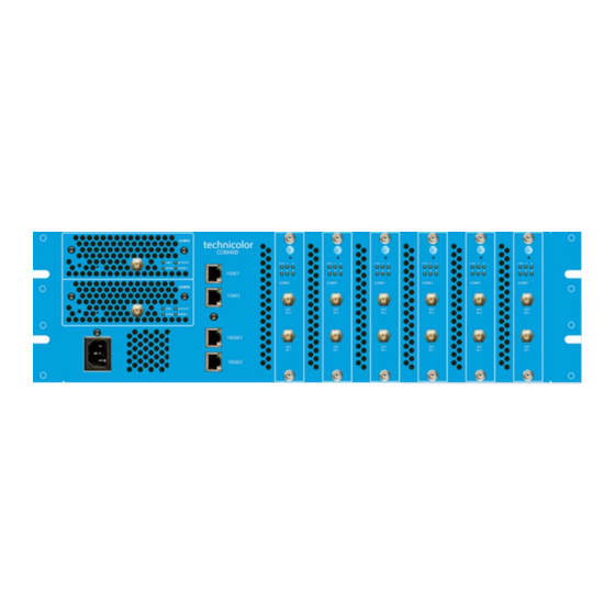
5 Mechanical Overview The following sections contain a brief overview of the devices that you will be interacting with along with the associated hardware. The intent is to give you a working knowledge of how the system operates under normal circumstances. COM400 Chassis Figure 3 below is a front and rear view of the COM400 chassis. -
Page 18: Com51 Card
➢ Compatible with legacy COM360 chassis and QAM6 modulators ➢ Manual software updates via internal TFTP server. ➢ Queries Technicolor update server for software updates at bootup and at daily intervals, downloads and installs software automatically. o Server will instruct COM51 to complete update at a prespecified time in early AM hours. -
Page 19: Com51A
COM51A COM51A is a specially configured COM51 card which works only with the Technicolor NTSC-8 analog modulator. ➢ It will not stream signal to a QAM or ethernet port. ➢ Only the NTSC-8 will receive data from a COM51A. The unit is software upgradable to a standard COM51 for upgrade purposes. -
Page 20: Qam20
High range – channels 26-158 ➢ New User interface makes configuration easier than the QAM6 in COM2000. ➢ QAM Licensing is the responsibility of the Product Distributor. Technicolor will not provide QAM upgrade licenses to fielded units. w w w . t e c h n i c o l o r . c o m / m c s... -
Page 21: System Connections
8 System Connections Figure 6 below illustrates connections to a COM3000 system. Figure 6 - COM51 System Diagram w w w . t e c h n i c o l o r . c o m / m c s... -
Page 22: Pre-Installation
Pre-Installation The COM3000 System is quite a bit different from the AT&T / DIRECTV set-top box (STB) receiver traditionally used in these installations. The COM3000 does not natively decode any audio or video, instead relying upon other devices in the system to decode and display the MPEG streams it produces. - Page 23 ➢ Prior to installation, it is recommended that a detailed site survey is conducted. Listed below are some key points to check and plan for during and after site survey. ODU Location ➢ Determine an area with clear line of site to the southern sky. ➢...
- Page 24 Inventory and Evaluation of Customer’s Televisions ➢ TVs must be capable of displaying Pro:Idiom encrypted MPEG-4 programming. Knowing what displays you will be working with is critical to a successful installation ➢ Familiarize yourself with Television programming requirements. ➢ Considerations: o Is a proprietary software required to create programming files? o Is there an onsite server for programming broadcast? o What is involved in loading channel lineups to the TVs...
-
Page 25: Distribution Networks
➢ Switches must be enabled for IGMP (Internet Group Management Protocol) ➢ Network Cabling must be installed in accordance with industry standards ➢ COM3000 provides layer two switch in COM400 chassis with IGMPv2 snooping. Existing Video Services Careful consideration should be focused on any existing services that will remain on the distribution network. -
Page 26: External Video Sources
➢ Research and familiarize yourself with all required television programming procedures. ➢ Non-compatible TVs can be used with a Pro:Idiom set back box such as the Technicolor DCI401MCS w w w . t e c h n i c o l o r . c o m / m c s... -
Page 27: Installation Guidelines
➢ DSWiM input to input 1 support 16 tuners ➢ SWiM 8 may be used on input one for 8 tuner configurations. ➢ The COM3000 system is designed to operate properly in ambient environments of 104 °F (40°C) or less. -
Page 28: Getting Started
17 Getting Started 17.1 Assembly ➢ Carefully unpack and install the QAM20 and COM51 cards in the COM400 Chassis as shown in Figure 7. Be sure to line up the cards with the guides in the chassis. ➢ After inserting the COM51 card finger tighten the two thumb screws to secure the card in the chassis. -
Page 29: Setting Up Multiple Chassis
17.2 Setting up Multiple Chassis 17.3 Chassis Dipswitch For multi-chassis installations each chassis will need to be assigned a unique chassis ID. ➢ The COM400 chassis has a default setting as chassis one. ➢ Chassis identification is configured via a dipswitch on the backplane circuit board. ➢... -
Page 30: Chassis Dipswitch Settings
DOWN 192.168.3.194 18 System Power Up Once assembled and connected to RF distribution power up the COM3000 by plugging in the power cord. There is no external power switch. 18.1 System startup LED Behavior The COM51 card has 6 LEDs on the front panel the top three are: ➢... -
Page 31: Boot Up
Boot up Upon powering up the COM51 cards LEDs will go through a series of flashing indicating boot up. Figure 10 below describes the LED activity during boot and normal operation. LED 1 LED 2 LED 3 Stage Note Power Off Normal Boot Power On Normal Boot... -
Page 32: Led Behavior After Boot Up
18.2 LED Behavior after Boot up Once the COM51 has successfully booted the LEDs will provide operational information as shown below in Figure 11. LED 2 LED 3 SWM error FLASH SWM error while APG acquisition SWM error HW initialization (FPGA loading) FLASH APG acquisition Running FLASH OFF... -
Page 33: Com400 Chassis
19 COM400 Chassis The COM400 chassis incorporates a Microsemi WebStax Layer two Ethernet Switch. Installations using RF plant have no need to access the chassis switch. IPTV installations should be aware of the switch and its default settings: 19.1 Accessing the COM400 User interface ➢... -
Page 34: Igmp Activation
IGMP Activation IGMP Snooping is enabled by default, to access IGMP Snooping Configuration navigate to: Configuration>IPMC>IGMP Snooping>Basic Configuration as shown below in Figure 14. Be sure Unregistered IPMCv4 Flooding in not enabled Figure 14 - IGMP Snooping Settings 19.3 IGMP Port Settings Router Port Specify which ports act as router ports. -
Page 35: Com400 Software Version
19.5 COM400 Software Version COM400 chassis software, like all system components should be kept current. To determine the software level of the chassis, navigate to the active Image Select section as shown below in Figure 16: ➢ Maintenance>Software>Image Select Figure 16 - COM400 Software Version 19.6 COM400 Software Update To upgrade COM400 software navigate to the Upload section as shown in Figure 17. -
Page 36: The Com3000 Web Interface
➢ Accessed by entering the IP address of one of the COM51 cards in the system into a web browser’s address bar. ➢ Chrome is suggested browser ➢ Clicking on the Technicolor logo on the Introduction Page in Figure 18 will open the COM51 Discover page. ➢ By default, card one in chassis one is always 192.168.3.18. -
Page 37: User Passwords
20.1 User Passwords To facilitate increased security the COM51 user interface is locked via a user password. The default password is, “com3k”. Lock status is specific to the IP address of the PC used to log in. Once the system is unlocked it will remain unlocked for 8 hours for the PC connected. When you first access a COM system you will be prompted to enter a password as shown below in Figure 19. -
Page 38: Com51 Tuner Licensing
Figure 21. The first number represents the number of licensed tuners, the second represents the number of SWiM frequency slots available. ➢ Tuner licensing is the responsibility of the Distributor who provided the equipment. Technicolor will not add tuner licensing to fielded COM51 cards. - Page 39 ➢ The final verification of licensing is in the COM51 SysLog. A COM51 exceeding the license count will display the following message in the Syslog: user.err syslog: a: ***Need Tuner License File: tuners=8; w w w . t e c h n i c o l o r . c o m / m c s Page 39...
-
Page 40: Overview Page
22 Overview Page The Overview Page shown below in Figure 23 provides a streamlined method for initial configuration and quick status monitoring of the COM3000 system using a series of pulldown menus to configure each card. ➢ The Overview page displays the same status information as the Discover page as well as encryption method being used and overall card status. -
Page 41: Qam Summary
22.1 QAM Summary The QAM summary portion of the Overview tab shows basic information about the QAMs mounted in the system. Figure 24 - QAM Summary ➢ Chassis – The QAM chassis number is determined by the COM400 chassis designation and QAM slot. -
Page 42: Channel Tuning Options
22.3 Channel Tuning Options ➢ The chassis and slot number hyperlinks in the Chassis and Slot columns allow you to collapse the display for the selection so that multiple cards and chassis can be more easily displayed. Chassis number hyperlink Slot number hyperlink ➢... -
Page 43: Figure 26 - Channel Selection Drop Down
Channel - Figure 26 shows the Channel dropdown feature. This allows you to assign a tuner to any channel in the guide data, including channels not authorized. If SD Duplicates is selected both HD and If Hide SD duplicates is selected only the SD channels will display HD channels will display Figure 26 - Channel Selection Drop Down... -
Page 44: Figure 29 - Bitrate Display
Bitrate - Figure 29 shows the Bitrate field. ➢ Displays a snapshot of the bitrate at the QAM20 port associated with the selected QAM major/minor channel. In the example QAM ch 33-2 is streaming 5.9 Mbps. ➢ If the stream is not routed to a COM20 card the Bitrate will read 0.0. Figure 29 - Bitrate Display SNR and Strength - Figure 30 shows the SNR and Signal Strength Display. -
Page 45: Discover Page
23 Discover Page Most configurations on the COM3000 system can be done via the Overview page previously discussed. However, there is redundant information in the Discover page and links to advanced edit pages for feature configurations and troubleshooting. ➢ The COM51 card issues a discovery call for all other COM51 (and COM46) cards in the system and populates a table with basic information on current tuning parameters and RF signal levels. -
Page 46: Explanation Of Discover
23.1 Explanation of Discover Page Fields Chassis - This field reports a unique identifier for the chassis. ➢ In systems that contain multiple chassis, this can be used to identify each chassis in the system. ➢ See Section 4.1 on how to assign unique identifiers to multiple chassis within a system. Slot - This field identifies the card’s location within a chassis, numbered 1 through 6. - Page 47 COM51. ➢ For optimum performance of the COM3000, this value should be somewhere between -25 and -55. ➢ If the Strength is low, it will be highlighted in yellow and if the Strength is very low, it will be highlighted in red.
-
Page 48: Advanced Edit
Overview screen. ➢ Channels entered in this screen will tune to HD programming. This can be helpful when tuning local channels not easily identified as High Definition © 2012 Technicolor. All Rights reserved... -
Page 49: Advanced Tune
24.2 Advanced Tune The Advanced Tune page can be used to change the main tuning parameters of a channel. Additional parameters can be accessed by clicking the Advanced Edit hyperlink at the bottom of the Basic Tune screen, which navigates to the Advanced Tune screen shown below in Figure 33. Information identifying the chassis / slot / tuner and card IP address currently being addressed is displayed at the top of the page below the command links. - Page 50 Dest_Port_Number - This field represents the destination port of the IP address you wish to stream to. Protocol_Type - This field is used to control whether the COM51 streams the data in UDP or RTP packet structures. The default value is UDP. Channel_Object_ID - This field is the data that the COM51 uses for tuning purposes.
- Page 51 Stream_ID - This field is optional and allows a unique identifier to be applied to every video stream produced by the COM3000 system. ➢ The allowable values for this field are any whole number between 1 and 65535. This field is to be left as default for normal operation.
- Page 52 Security_Mode - Typically, this field will not need to be changed. The only settings most should be concerned with are: ➢ None - Setting will only work on AT&T / DIRECTV channel 100. This allows you to turn Pro: Idiom encryption off so that a standard HDTV or PC-based utility like VLC Media Player can be used for troubleshooting.
-
Page 53: Informational Status
24.3 Informational Status The Info section, shown below in Figure 34, provides a view of many key indicators to the operation of the COM51 card. ➢ A concise index to the characteristics of each individual COM51 card according to its status and user-defined settings.. -
Page 54: Figure 35 - Network Id And Frequency Index
The table below in Figure 35 details the Network_ID numbers and corresponding satellite. Network_ ID Satellite 10-11 14-15 In the example below, we are looking at CNN HD: Network ID = 10 Satellite 99 Frequency Index= 17 +1 Transponder 18 Figure 35 - Network ID and Frequency Index Authorized - This field provides feedback on whether the card has been authorized within the AT&T / DIRECTV network. -
Page 55: Com51 Led Control Feature
Blackout - This field can be used to determine whether AT&T / DIRECTV has issued a blackout of the content on a channel. This is a good thing to investigate if the video suddenly stops playing on any channel, but it is particularly likely to happen with nationally televised sporting events. -
Page 56: Com51 Cam Log Data
24.5 COM51 CAM Log Data This section gives you the ability to read the log files generated by any COM51 card’s Conditional Access Module (CAM), also known as its smart card. The messages reported here match the ones that may be seen on a normal set-top box and can be used to determine whether the card has been properly authorized and paired. -
Page 57: Com51 Software Reset
(all others are for development purposes only): 1 = MT – This option allows you to upload the special MediaTune authorization and channel guide files. See COM3000 Technical Support - Mediatune Installation Folder on the Technicolor / MCS website for details. -
Page 58: Com51 User Configuration Options
Filename - This value entered in this field tells the COM51 which file to download (in the case of software updates and license files), or what name you want to give the log file being transferred from the card. Mode – Must be set for TFTP 24.8 COM51 User Configuration Options This section gives you the ability to customize select features of the COM51 cards to better suit your application. - Page 59 4 = Fixed - In this mode the user sets the Base_IP, Subnet and Gateway fields. All fields MUST be set. A Gateway MUST be defined regardless of it being there or not for this mode. Once you set the card IP you must reboot the card. 8 = No Change - This setting does not actually represent a separate mode, but rather acts as a way to tell the COM51 card that you would like it to continue using whatever mode it is currently using.
- Page 60 NTSC-8_IP – Enter the IP address of a NTSC-8 to be fed from this COM51 card. NTSC-8_tunercount – COM51 cards will stream 1-23 tuners to NTSC-8. ➢ Enter the number of tuners you are using for NTSC-8s. One COM51 card will stream 23 channels and a program guide to NTCS-8.
-
Page 61: Com51 "Direct Tune" Feature
➢ This section gives you a method to force a tuner to a satellite and transponder pair. ➢ This can be useful when attempting to track and isolate RF problems with the COM3000 system. The data required to perform this operation can be gathered from the basic “Tune” interface shown in the advanced tune section (see Figure 33 - Advanced Tune Screen ) ➢... -
Page 62: Using The Vidplay Feature
The VidPlay Feature is no longer available due to changes in the Western Digital My Cloud NAS drive software. It is recommended to use an inexpensive PC and VIDplay.exe software provided by Technicolor. Figure 44 - Vid Play 24.12 Setup for Vidplay.exe ➢... - Page 63 ➢ Navigate the COM3000 QAM tab and verify it is streaming to the QAM Port 20 ➢ In this case the video will play on ch 23-4 ➢ The video will continue to play in a loop until the DOS window is closed.
-
Page 64: Using The Com51 "Simulcrypt" Feature
24.14 Displaying COM3000 Status By clicking the Display hyperlink at the top of any COM3000 web interface page, you can see the information last displayed on the Discover Screen w w w . t e c h n i c o l o r . c o m / m c s... -
Page 65: Pairing Info
25 Pairing Info By clicking the PairingInfo hyperlink at the top of any COM3000 web interface page, you can quickly evaluate the authorization status of all cards in the system. ➢ In the example shown in Figure 45, all cards are activated and paired ➢... - Page 66 Following is a detailed list of information available on the PairingInfo page. Chassis - This field reports a unique identifier for the chassis. In systems that contain multiple chassis, this can be used to identify each card in the system. ➢...
- Page 67 Up_Time – This field gives an indication of how much time has elapsed since the card was last rebooted or powered up. Upgrade – By checking this box for a particular card, you will make each of the fields at the bottom of the screen active for that card.
- Page 68 4= License – This option allows you to load various software licenses to enable new modes and features in the COM51. One example might be upgrading the COM51-A to HD mode after purchasing software license upgrade from Distributor 7 = KeyRenewal – This option will send a Pro:Idiom key renewal to any TV tuned to a RF channel on the card selected.
-
Page 69: Tune All
The information shown in Figure 47 below is the result of clicking the TuneAll hyperlink at the top of the COM3000 web interface page. ➢ This section provides a practical way to configure an entire COM3000 system with minimal effort. ➢... - Page 70 The text in the tuning table take the following form (see Section 1.1 for more on tuning): ➢ Chassis-Slot-Tuner, IP_Address:Port_Number, Major_Number-Minor_Number-Security_Mode; ➢ The sample line below indicates the 1st tuner of a card residing in Slot #4 of Chassis #2. It is targeting Port 301 of the device residing at the IP address 192.168.4.245 and tuned to the HD broadcast of channel 242 with Pro:Idiom encryption set.
-
Page 71: Help
27 Help The Help tab provided a short reminder of the functions of each tab on the COM51 user interface as shown below in Figure 48. Figure 48 - Help Tab 28 SysInfo The Sysinfo tab shown below in Figure 49 provides important information about the COM51 status. -
Page 72: Healthinfo
By clicking the HealthInfo hyperlink at the top of any COM3000 web interface page, you will access the page shown below in Figure 50. The data available here gives you an indication of the overall health of the COM3000 system and can be used to identify potential problem areas at a glance. -
Page 73: Epg
➢ Fan1 Health – This field reports the health for Fan 1. If the fan is connected and operating properly, the value should return “OK”. If there is a problem the value will return “Fault”. 30 EPG See Section 32 EPG Overview w w w . -
Page 74: Syslog
Figure 51 above shows a SWiM error occurred and cleared in less than two seconds. In addition to clicking the Syslog hyperlink at the top of any COM3000 web interface page, the syslog data may also be accessed directly from the PairingInfo screen by clicking directly on the hyperlinks for each card’s IP address. -
Page 75: Epg Overview
All AT&T DIRECTV networks tuned on the system o Channels from external sources. ➢ COM3000 EPG has the ability to store and stream welcome screen images to the QAM that will play direct from the COM51 card. o See section 33.1 for details on creation of Welcome Screen images. - Page 76 channel, set the port number to -1. If the DestIP is a valid IP address but the DestPort is 0, then the EPG channel is disabled but PSIP guide generation is still enabled. This makes it possible to have one card provide PSIP data and a separate card provide guide only. ➢...
-
Page 77: Guide.xml Overview
32.1 Guide.XML Overview Technicolor has developed an interactive guide feature that works exclusively with the DCI401MCS set back box. ➢ DCI401MCS must be running software version 01.22.11 or newer. Setup is similar to the instructions for EPG. ➢ Leave the IP field set to 1.2.3.4 ➢... -
Page 78: Getting Started With Epg
32.2 Getting Started with EPG Access the EPG setup screen shown in Figure 54 below, click the EPG hyperlink at the top of any COM3000 web interface page. Figure 54 - COM3000 EPG Page Following is a brief explanation of each field available on the EPG page as shown above: ➢... - Page 79 ➢ hd|sd - This tells the guide whether to pull the data for the HD or the SD version of a particular channel. The default behavior for the COM3000 is to look for HD channels, so this setting allows you to add SD channels to the EPG if needed. Please note that on submission, the EPG will default to ‘hd’...
-
Page 80: Figure 55- Com51 Epg Load
The screen shown in Figure 55 below is the result of clicking the EpgLoad button located at the bottom of the EPG screen. Doing this provides a convenient starting point for building an EPG for your system. To set a custom channel map change the RF channels listed to the preferred channel ring. -
Page 81: Epg Customization And Channel Mapping
32.3 EPG Customization and Channel Mapping Program Guide can be customized to serve two purposes: ➢ Match the guide information to the property channel lineup. ➢ Insert PSIP data to facilitate channel mapping and programming information. Note: check with television manufacturers for PSIP and channel mapping functions in Hospitality environments To customize the EPG to match the property’s lineup you will need to edit the EPG data ➢... -
Page 82: Logo Creation And Upload
32.5 Logo Creation and Upload The COM51 has a built-in facility for superimposing a property’s logo into the upper right corner of the EPG. ➢ A logo file must be a 24-bit bitmap (*.bmp) file and can be no larger than 170x60 pixels in size (170 pixels wide and 60 pixels long). -
Page 83: Welcome Screen
33 Welcome Screen The welcome screen feature allows the creation and playback of up to 10 static images on a QAM channel. ➢ Each welcome channel will use the EPG function on a card not currently being used for EPG or Guide.XML ➢... - Page 84 ➢ Next open the file in Microsoft Paint. ➢ Use the Resize and Skew feature to set the image to 720X480 as shown in below in Figure 61. o Select Resize by Pixels o Set Horizontal to 720 o Set Vertical to 480 o Uncheck Maintain Aspect Ration o Click “OK”...
-
Page 85: Figure 61 - Welcome Screen Settings Using Microsoft Paint
Figure 61 - Welcome Screen Settings Using Microsoft Paint ➢ Image will resize to correct format as shown below in Figure 62. Figure 62 - Correctly Sized Welcome Screen Image ➢ Save file!!! ➢ Repeat the above procedure to create multiple screens, welcome2, welcome3, etc. Note file names must be lower case with no spaces. -
Page 86: Uploading Welcome Screens To Com3000
33.2 Uploading Welcome Screens to COM3000 Determine Card to use: ➢ Log into a COM51card not currently running EPG ➢ Navigate to the COM51 Pairing info tab ➢ Upload welcome images one at time to the cards tftp section as shown below in Figure 63. -
Page 87: Adding Welcome Screens To Guide Data
33.3 Adding Welcome Screens to Guide Data Welcome screens should be included in EPG /IPG programming to facilitate channel mapping and inclusion in EPG / IPG guides. ➢ Enter the welcome screen channel and mapping information into the guide as if it was any other external source being modulated by the QAM20. -
Page 88: Qam20
34 QAM20 The QAM 20 setup is very different than the QAM6 COM 2000 unit. Output RF channels can be assigned to induvial QAMs and the setup has been streamlined. 34.1 Accessing the QAM Page The QAM tab of the COM51 user interface can be accessed in one of two ways: ➢... -
Page 89: Checking Software Version And License Count
34.2 Checking Software Version and License Count Before beginning installation verify: ➢ QAM software version matched the latest available on the Technicolor website. ➢ The license count is correct for your installation and matches the bill of materials from your distributor. - Page 90 The three boxes at the bottom of the control screen are used to reference the following: ➢ Index= Sets the QAM index referenced in the first column of the QAM table. By default the field is populated with -1. As a security measure you must delete the -1 and enter the QAM Index. ➢...
- Page 91 Figure 72 -QAM Table w w w . t e c h n i c o l o r . c o m / m c s Page 91...
-
Page 92: Setting Unique Rf Output To A Qam
34.4 Setting Unique RF output to a QAM RF channel outputs can be assigned to an individual QAM or group of QAMS To set a unique RF output to an induvial QAM: ➢ Enter the QAM number in the Index box ➢... -
Page 93: Setting Unique Outputs To A Group Of Qams
34.5 Setting Unique outputs to a group of QAMs A group of QAMs can be set to a unique group of output channels: ➢ Enter the first QAM to be set in the Index box ➢ Enter the channel number in the Freq box ➢... -
Page 94: Troubleshooting
35.2 Verify RF Before troubleshooting the COM3000 verify satellite signal passes EIV check on the DIRECTV AIM meter at the COM51 input. Use a test TV and field strength meter to test picture quality directly from the COM3000 QAM output. ➢... -
Page 95: Troubleshooting Common Problems
Figure 77 - COM51 Reset 35.4 Troubleshooting Common Problems The most common problems encountered with the COM3000 systems are due to poor RF signal conditions or to bad or loose connections. Before moving on to detailed troubleshooting of any problem, you should check the following: ➢... -
Page 96: Preventing Pro:idiom Key Loss
37 Simultaneous QAM and Multicast IP Output (Currently under development and testing as of May 2018) The COM3000 system is capable of outputting both IP and QAM signals simultaneously. There are certain limitations to sending programming from a COM51 to a multicast address and the QAM20 simultaneously. - Page 97 TV rings, or to install separate COM3000 systems for IP and RF. w w w . t e c h n i c o l o r . c o m / m c s...
-
Page 98: Syslog Server Setup
38 Syslog Server Setup The COM51 card syslog retains 500 lines of text for review in troubleshooting. Old entries are deleted as new entries are added. To preserve syslogs for a longer period for troubleshooting a syslog server may be set up on a local PC. There are multiple syslog programs available. - Page 99 From the Advanced Edit page scroll to the User Config section: Enter PC IP address Enter the IP address of your PC in the “LOG_IP” field. Leave the “Log_Level” field blank. Repeat this step for each card you want to capture logs from. Reboot the card(s) Create a directory named “syslog”...
- Page 100 In the TFTP settings menu go to SYSLOG check the “Save syslog messages” box and enter the file location in the “To file” field: Click OK Click Box File Location From the TFTP main screen select the “Syslog Server” tab. You will see the syslog information displayed in the text box, designated by the IP address of the card in the “from”...
-
Page 101: Open Software Notification
Technicolor's website at the following address: http://www.technicolor.com/en/hi/minisites/open-software or at another address as Technicolor may provide from time to time. If and where applicable, depending on the terms of the applicable Open Source Software licenses, the source code of the Open Source Software is available for free upon request. - Page 102 w w w . t e c h n i c o l o r . c o m / m c s Page 102...
Need help?
Do you have a question about the COM3000 and is the answer not in the manual?
Questions and answers