Table of Contents
Advertisement
Advertisement
Table of Contents

Related Manuals for Aichi SR-123J


Summary of Contents for Aichi SR-123J
- Page 1 SELF-PROPELLED CRAWLEF TYPE t'itORK PLAT FoRro...
-
Page 2: Operator Qualifications
THIS SAFETY ALERT SYMBOL MEANS ATTENTION TO A HAZARD! YOUR SAFETY IS INVOLVED BE ALERT. Red Danger Labels are used to indicate the presence of a hazard that will cause death or serious injury. Orange Warning Labels are used to indicate the presence of a hazard that may cause death or serious injury. -
Page 3: Tip-Over Hazard
OPERATING THIS MACHINE WITHOUT THE CORRECT SAFETY HARNESS ATTACHMENT COULD RESULT IN SERIOUS INJURY OR DEATH. 491-0000148 ATTACH NOTE Aichi is continuously improvina and expanding SAFETY product features on its equipment; therefore, specifications and dimensions are subject to ",NYARD change without notice. -
Page 4: Platform Capacity
WARN! OTHER HAZARDS . DO NOT EXCEED RATED LOAD. . DO NOT USE IF WORK PLATFORM IS NOT WORKING PROPERLY OR IF ANY PART IS DAMAGED, MISSING, OR WORN. . DO NOT USE NEAR MOVING VEHICLES OR CRANES. 4. DO NOT USE WITHOUT GUARDRAILS, MIDRAILS, ENTRY GATE, OR MIDRAIL BAR IN PLACE. 5. -
Page 5: Minimum Safe Approach Distance
1 \ WARNING You are required by ANSI/SIA A92.5 1990 to read and understand YOUR RESPONSIBILITIES OPERATORS MANUAL before you use or operate this work platforrn. The Operators Manual must always be attached to the work platform. FAILURE TO COMPLY with your REQUIRED RESPONSIBILMES in the use and operation of the work platform could result in DEATH OR SERIOUS INJURY. -
Page 6: Specifications
SPECIFICATIONS SR-123J ISR-403J Model 8,600 kgf 18,960 lbs W. it Overall weight 0.74 kgf / c m 2 Max. ground contact pressure 11 PSI A-4JB1-PAA17 Model < 169 in' Total displacement 2,771 cc 41.5kw / 2,200 rpm 56.4 PS / 2,200 rpm Output power 19.4 kgf-m /1,800 rpm 140 ft-lb / 1,800rpm... - Page 7 ..m u m " , 1 1 1 1 1 - 0 1 .- • i iiiii _______ i i i ■ M u I -i ..1 IIII 1 1 1 1 9m i r -winig ' 1 1 I t , .
- Page 8 Travelling restriction arcas Rated load : 250kgf (550Ibs) 3 6 0 0 iiksVit i l k ' k 4 k (32.8') l O - v - k \ N 4 4 v r \ k . . . v L 1 \ t -%■•■■...
-
Page 9: Section 1 Iiiitroduction
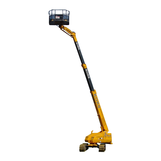
SECTION 1 IiiITRODUCTION PURPOSE OF EQUEIMENT Aichi Work Platforms are designed to transport and raise personnel and tools to overhead work areas. USE OF EQUIPMENT The crawler type work platform (Figure 2) (hereafter referred to as work platform) is a rugged and highly maneuverable, mobile work station. -
Page 10: Section 2 Operation
SECTION 2 OPERATION OPERATOR QUALIFICATIONS Only authorized people who have been trained should use this work platform. Safe use of this work platform requires the operator to understand operating procedures, operators responsibility for maintenance, limitations and warnings. The operator must understand and be familiar with this manual, its warnings, and all warnings and instructions on the work platform. -
Page 11: Lower Control Panel
LOWER CONTROL PANEL Figure 4. Lower Control Panel 1. HOUR METER 2. REMOTE CONTROL SOCKET FOR TRAVEL FROM BASE (OPTION) 3. BASE/PLATFORM CONTROL SELECTOR SWITCH 4. BOOM ELEVATION/LOWERING SWITCH 5. EMERGENCY PUMP SWITCH 6. BOOM EXTENSION/RETRACT1ON SWITCH 7. HIGH THROTTLE SWITCH 8. - Page 12 LOWER CONTROL PANEL 1. HOUR METER - Activated when the engine is started, measures engine run time. 2. REMOTE CONTROL SOCKET FOR TRAVEL FROM BASE (OPTION) - This option is used to move the work platform from the ground position. 3.
- Page 13 LOWER CONTROL PANEL (continued) 13. GLOW PLUG LAMP - This lamp will tell the operator when it is safe to start the engine. Turn the "engine start/stop key switch" to the "H" position until the lamp glows, then start the engine. 14.
- Page 14 Horn s/w Platform rotation s/w Accelerator s/w Fly jib s/w Emergency pump s/w Working light s/w Rotation control lever Extension control lever Elevation control lever Travel(L) control lever Travel(R) control lever Emergency stop s/w Engine start s/w ĺl 9 04. Platform level s/w </ view...
-
Page 15: Platform Controls
PLATFORM CONTROLS Figure 6. Platform Controls • . FOOT SWITCH 2. HIGH THROTTLE SWITCH 3. FORWARD/REVERSE TRAVEL CONTROL LEVERS 4. LEFT TRACK CONTROL 5. ENGINE START SWITCH Foot Switch 6. POWER LAMP 7. RIGHT TRACK CONTROL 8. BOOM ELEVATION/LOWERING CONTROL LEVER 9. -
Page 16: Safety Devices
PLATFORM OPERATiNG CONTROLS (con tinu ed ) RIGHT TRACK CONTROL - Pushing forward will cause the right track to go forward. Pulling it back will causethe right track to go in reverse. 8. BOOM ELEVATION/LOWERING CONTROL LEVER SWITCH - This switch is used to raise and lower the boom. -
Page 17: Operating Procedures
OPERATING PROCEDURES WHEN ARE YOU AUTHORIZED AND QUALIFIED TO OPERATE THE WORK PLATFORM READ AND UNDERSTAND OPERATOR QUALIFICATIONS WARNING 1. Only qualified operators who have read and understand this manual should operate this machine. 2. Protective clothing should be worn before using the work platform. 3. - Page 18 OPERATING PROCEDURES (CONT.) DANGER 14. Danger tip over hazards A. Do not elevate or drive elevated on soft or uneven surfaces. Note: Maximum contact pressure is 9.4 PSI on ISR-403, 11 PSI on ISR-602, and 13 PSI on ISR-700. B. Do not pull or push against any object C.
-
Page 19: Start And Operation
START AND OPERATION Pull the Emergency Stop Button out. 2. Select platform on the Base/Platform control selector switch. 3. Enter the platform by swinging the midrail entry bar in (if equipped), or raising the midrail entry bar. 4. Attach harness and lanyards of each occupant to the lanyard anchors. 5. - Page 20 START AND OPERATION (continuO) 12, RIGHT TURN (Forward stopped) - With the "right" lever in the stop position, push the -left" lever forward. 13. LEFT TURN (Spin stopped) - Pull the "left" lever to reverse and push the "right" lever forward. 14.
- Page 21 WORK PLATFORM SHUT DOWN PROCEDURE 1. Completely retract the boom and lower the platform. 2. Push the Emergency Stop Button, turn the Key Switch to the off position and remove the key. 3. Remove all tools and materials from the work platform. LOADING AND TIE DOWN PROCEDURE NOTE: THE FOLLOWING INSTRUCTIONS ARE INTENDED TO AID IN THE LOADING AND UNLOADING OF THE WORK PLATFORM FROM A TRUCK BED.
-
Page 22: Section 3 Maintemance And 3Eavice
SECTION 3 MAINTEMANCE AND 3EaViCE OPERATORS RESPONSIBILITY FOR MAINTENANCE Death or serious injury can result if the work platform is not inspected or maintained. Inspection and mainte- nance should be performed by qualified people in conformance with the manufactures recommendations. The operator should always check to see that the work platform has been inspected and maintained before using The operator should perform all the daily inspections found in Table 3, Maintenance and Inspection Schedule. - Page 23 MAINTENANCE AND SERVICE (continued) HYDRAULIC SYSTEM AND COMPONENT MAINTENANCE AND REPAIR The points listed below should be kept in mind when working on the hydraulic system or any component. 1. To prevent failure of structual parts or hydraulic components, relief valves which limit pressure to safe operating values are included in the hydraulic circuits.
Need help?
Do you have a question about the SR-123J and is the answer not in the manual?
Questions and answers