
Related Manuals for Aichi SR12C


Summary of Contents for Aichi SR12C
- Page 1 Operation Manual with Maintenance Information Models SR12C SR14CJ NOTICE Read this manual before operating.
- Page 2 Serial Number Range: after 711607 - Current Copyright Part Number: FS-342S © AICHI CORPORATION. All rights reserved. January 2009 No part of this manual may be reproduced in any form, in an electronic retrieval system or otherwise, without the written permission from AICHI, except for personal use or other cases permitted by copyright laws. Contact us: Head offi ce 1152 Ryoke Ageo Saitama 362-8550 Japan This machine has been TEL: +81-48-781-1111 manufactured to conform to http://www.aichi-corp.co.jp European Standard EN280.
- Page 3 Important Information Thank you very much for making your • Perform all maintenance described purchase from AICHI. in this manual and in the designated Please operate and use the machine service manual for the machine. correctly. • Constant improvement of its products is • Operation of the machine not in AICHIʼs policy. Therefore, specifi cations accordance with this manual, incorrect of the machine are subject to change operation, incorrect checking, and without prior notice. incorrect maintenance may lead to • The fi gures illustrate the cautions listed injuries, death, and may damage the in this manual. The purpose of the machine. fi gures is to identify important points. In • Read, understand and obey this manual some cases the shapes may be diff erent before using, checking or maintaining from those of the product you have the machine. purchased. • Comply with employer, job site and • This manual must be kept with the ...
- Page 4 Safety Alert Symbol and Owner and User Signal Words Responsibilities This is the safety alert All owners and users of the machine symbol. It is used to alert must read, understand, and comply you to potential personal with all applicable regulations. Ultimate injury hazards. Obey all safety compliance to national safety regulations messages that follow this is the responsibility of the user and their symbol to avoid possible employer. injury or death. Operator Qualifi cations The signal words, “DANGER,” “WARNING,” and “CAUTION” identify the degree of Operator of the machine must receive latent hazard and its level of seriousness. safety training to ensure safe operations. Incorrect use of the machine can cause DANGER serious injury or death. All personnel are requested to receive Indicates a hazardous situation which, if safety training and only trained and not avoided, will result in death or serious authorized personnel are permitted to injury. operate the machine. Use this manual for WARNING safety training. Operator of the machine must not Indicates a hazardous situation which, undertake responsibility for the machine if not avoided, could result in death or operation until enough training has ...
-
Page 5: Table Of Contents
Table of Contens 2‒2‒1 Hydraulic Oil Specifi cations ......26 Safety Rules ......1 2‒3 Check the Battery Fluid Level ....27 1. Electrocution Hazards ........1 2‒4 Check the Engine Oil Level ......27 2. Tip Over Hazards ........... 1 2‒4‒1 Engine Oil Viscosity ........27 3. Fall Hazards .............. 3 2‒5 Check the Cooling System ......27 4. Collision Hazards ........... 4 3. ... - Page 6 2‒1 Upper Controls (from platform) ....41 2‒2 Lower Controls (from ground) ....42 Transporting ......43 1. Preparations for Transporting .....43 2. Tie Down ..............44 3. Hoisting the Machine ........44 4. Hoisting with Boom Raised......45 Storage ........46 Specifi cations ......47 1. General Specifi cations ........47 2. Work Range Diagram ........48 2‒1 SR12C ..............48 2‒2 SR14CJ ..............48...
-
Page 7: Safety Rules
Safety Rules • Do not use the machine during Electrocution Hazards lightning or storms. Stop operation in DANGER bad weather. • Do not use the machine as a ground for • This machine is not electrically welding. insulated. Do not use the machine near electric power lines. Tip Over Hazards • Keep a safe distance from electric power DANGER lines and apparatus. For safe distance, check your national or local regulations. • Do not exceed the platform capacity as If no national or local regulation is indicated on the serial number plate. available, use the table below. M085E200 fi g. 1‒2 M085E100 fi g. 1‒1 • Do not hang or attach loads to the machine. Spread loads evenly on the Voltage Minimum Safe platform. (Phase to Phase) Approach Distance 0 to 300 V... - Page 8 • Do not elevate the platform on soft or • Do not touch or be attached the uneven ground. platform to any nearby structures. M085E400 fi g. 1‒4 M07Y9501 fi g. 1‒7 • Do not elevate the platform on a slope. • Do not place things such as steel beams • Do not use the machine on a slope or power lines across the platform, and more than the maximum allowable tilt use the boom to lift them. angle. When the machine tilt more than the maximum allowable tilt angle, the tilt alarm buzzer sounds and the tilt warning light goes on. Never continue working after alarm sounds. Maximum allowable tilt angle: 5 ° Beep! M07Y9601 fi g. 1‒8 • Do not use the boom or platform More to push or pull power lines or other than objects. max. allowable tilt angle M085E500 fi...
-
Page 9: Fall Hazards
• Do not work by tying down the machine • Do not sit, stand or climb on the chassis, boom or platform to other guardrails, or jump from the platform to structures. another structure. M085E700 fi g. 1‒10 M07Y9A01 • Do not operate the machine where fi g. 1‒12 there are strong winds or gusts. • Do not elevate the platform when wind speeds may exceed 12.5 m/s. If wind speeds exceed 12.5 m/s when the platform is elevated, lower the platform and do not continue to operate the machine. • Do not increase the surface area that can catch wind, such as covering the platform with a sheet. The stability of the machine will decrease. M07Y9B01 fi g. 1‒13 • Do not use on a slippery or icy surface. If it is unavoidable, be sure to use nonskid • Do not climb up/down from the gears such as tire chains. platform when it is raised. • Do not disable or alter the switch. • ... -
Page 10: Collision Hazards
• Do not hit the ground with the platform. Collision Hazards WARNING • Before traveling, check the arrow decals affi xed on the chassis to make sure the traveling direction of the machine. Forward M085F100 (Green) fi g. 1‒18 • Once the platform is raised, do not allow people or things under the platform. Backward (Red) Forward Backward (Green) (Red) M085D122 fi g. 1‒15 • Make sure that no person or obstacle is around the machine. Be aware of blind M07Y9J02 spots when traveling or operating. If fi g. 1‒19 your vision is poor, have a guide to assist • Do not lower the boom unless the area you. below is clear of persons and obstacles. • The turntable protrudes 850 mm • ... -
Page 11: Damaged Machine Hazards
• If battery fl uid gets on the skin or on Damaged Machine Hazards clothing, wash it away immediately WARNING with cold water. If it gets into the eye, wash immediately with cold water, • Do not use a damaged or and seek ophthalmological treatment malfunctioning machine. Have it immediately. checked and repaired immediately. • The battery produces fl ammable • When operators are changed by work hydrogen gas, and there is a possibility shift, perform the pre-start checks at of explosion. Never allow anything every change. Perform the pre-start that can cause fi re close to the battery. checks on the operatorʼs responsibility. Charge the battery only under good • Perform the pre-start checks on fi rm, ventilation. level surface, with the platform lowered. Engine Safety • If the pre-start checks reveal any abnormalities, put an “Out of Order” Scald Hazards sign on the machine, and cancel the DANGER check at that point. -
Page 12: Personal Safety
Personal Safety Traveling Precautions • Surfaces on which you must avoid Fall Hazards traveling or working. DANGER DANGER • Always use a safety harness in the Never travel or work on the following platform. All persons in the platform surfaces. Doing so is very dangerous must comply with employer, work and may cause the machine to tip over area, and local and national safety or the platform to collide with building regulations regarding the use of structures. personal protective equipment. All (1) Do not travel or work on soft or uneven personal protective equipment must surfaces with level diff erences. In particular, comply with applicable regulations, ground foundations are unstable on earth and must be inspected and used in fi lls, around dug out trenches, and on the accordance with their manufacturerʼs shoulder of roads, and may give way due instructions. to the weight or vibration of the machine. • All personal fall protective equipment Particular caution is necessary after rain must be attached to only which may cause soil foundations to ... - Page 13 • When the machine must travel to a DANGER particular location and there is no other option but to travel on uneven surfaces, • Irrespective of how much the boom is up and down steps, or on slopes extended, never raise the boom angle exceeding the maximum allowable tilt to a position greater than horizontal angle, obey and observe as follows: while traveling as the machine will (1) Do not travel the machine on a slope incline on even minor bumps, steps, exceeding the machine gradeability. and slopes. The machine will become Failure to follow instruction could tip over unstable and the machine may tip over. the machine. The machine gradeability: This may result in serious accidents refer to Chapter 12. in which the worker on the platform (2) Traveling on slopes may become sandwiched between a (i) Climb perpendicular to the slope face building or structures. with the counterweight facing uphill. • Pay adequate attention when you (ii) Do not change direction or turn to the have no other option but to drive the side while climbing a slope face. Change machine for the purpose of moving it to direction after reaching level surface. a diff erent location. (i) ...
- Page 14 (v) Never travel with the boom raised. This may cause the machine to tip over when traveling on even slight uneven surfaces, steps, or climbing inclines. M085K801 fi g. 1‒25 (iv) The machine may suddenly incline when climbing down and over a top step. Pay attention to buildings and structures located above and below the platform. M085K901 fi g. 1‒26 M085KA01 fi g. 1‒27 M085KC02 fi g. 1‒28...
-
Page 15: Decals
Decals Symbol and Pictorials Defi nitions Read operation Read service manual. Crush Hazard Crush Hazard manual. Burn Hazard Body Injury Hazard Maintain required Do not lift. clearance. Do not wash Keep away. Do not step. No open flame. by high pressure. Do not touch. Keep off. Do not contact power Do not travel elevated Do not elevate platform No smoking. lines; do not touch on/near soft or uneven unless machine is on energized machine. surfaces. firm level surface. Sound power level in Platform Capacity Maximum Manual Maximum Wind decibels Force Speed M07Y0421... - Page 16 Symbol and Pictorials Defi nitions (Continued) Loads Maximum Wheel Load Platform Over Load System Failure (personnel and tools) Outreach limit Tilt Warning Lanyard Anchorage Lift Point Point Tie-down Point ON and OFF Enable Switch Pre-start Check Horn Fast Slow High Torque Engine Pre Heat Oil Pressure Water Temperature Air Filter Engine Start Engine Failure Emergency Pump Generator M07Y0522...
- Page 17 Symbol and Pictorials Defi nitions (Continued) Hydraulic Oil Oil level: High Oil level: Low Battery Fuel Diesel Fuel LPG Fuel Fuel Level Beacon Working Light Head Light Boom Rotation Boom Telescope Boom Elevation Platform Rotation Horizontal / Vertical Platform Level Adjust Fly-jib Elevation Platform Contact Movements Travel: Left Travel: Right Upper control / Off / Lower control Selection M07Y0821...
-
Page 18: Safety Signs And Locations
Safety Signs and Locations 491-0000706 494-0000571 491-0000654 491-0000650 491-0000654 491-0000650 491-0000654 491-0000152 491-0000654 494-0000575 491-0000696 491-0000670 491-0000653 491-0000670 (SR14CJ only) 491-0000159 5Y6-04167-00 182-01002 (Arrow Decal) 494-0000253 5Y6-04264-00 (SR12C) 5Y6-04165-00 5Y6-04166-00 491-0000673 491-0000649 494-0000574 (SR12C) (SR14CJ) 5Y6-04263-00 (SR14CJ) M085G522... - Page 19 Safety Signs and Locations (Continued) 5Y6-04264-00 (SR12C) 494-0000575 5Y6-04165-00 (SR12C) 491-0000669 5Y6-03927-00 5Y6-04263-00 (SR14CJ) 491-00891 5Y6-04166-00 (SR14CJ) 182-01002 494-0000253 491-0000652 491-0000670 (SR14CJ only) 491-0000693 5Y6-04167-00 (Arrow Decal) 491-0000650 494-0000575 494-0000575 494-0000578 491-0000682 491-0000650 S49431-11 494-0000577 494-0000577 (Caution Stripe) (Caution Stripe) 5Y6-03876-00 493-0000015 5Y6-03876-00 491-0000673 (Battery) 494-0000170 (Rotation Lock Pin) (Turntable) M085G622...
- Page 20 Safety Signs and Locations (Continued) 491-0000669 491-0000700 (Hydraulic Oil Tank) 491-0000701 (Inside Turntable Cover) 5Y6-03925-00 494-0000572 (Fuse) (Hydraulic Oil Tank) 378-0000024 (Thermo Label) (Fuse Holder) 494-0000573 (Hydraulic Oil Tank) H - H J - J (Inside Fuse Holder Cover) 491-0000557 (1 st Boom) 494-0000552 5Y6-03847-00 (6 ft Platform) 5Y6-03846-00 (8 ft Platform) 491-0000159 494-0000552 491-0000669 494-0000557 5Y6-03843-00 L - L 494-0000549 494-0000549 (Caution Stripe) (Caution Stripe) 491-0000557 494-0000549 491-0000557 (Caution Stripe) 494-0000549 (Caution Stripe) M - M 491-0000650...
-
Page 21: Safety Systems
Safety Systems Tilt alarm buzzer List of Safety Systems The tilt alarm buzzer sounds when the Relief valve machine tilts more than 5° . Protect the hydraulic components by If the tilt alarm buzzer sounds when the relieving abnormally high pressure in the platform is elevated, immediately retract hydraulic system. the boom, and lower the boom under the Single holding valve horizontal, and move to a fi rm, level surface. on Boom elevation cylinder Travel speed limit system Prevents the boom from natural descent in This system automatically limits the travel the event of hydraulic hose breakage. speed corresponding to various boom Double holding valve statuses. on Boom telescope cylinder For the specifi c function of this system, see Prevents the boom from natural descent in the section “2. Travel speed limit system.” the event of hydraulic hose breakage. Travel function limit system Double holding valve ... -
Page 22: Travel Speed Limit System
Travel Function Limit System This system disables the travel function corresponding to the boom status and the machine tilt angle as follows. Area Boom Status Machine Tilt Angle Travel Function Elevation: ≧ 15 ° ≧ 5 ° Disable Telescope: Min〜Max < 5 ° Available Elevation: < 15 ° ≧ 5 ° Disable Telescope: Not fully retracted < 5 ° Available Elevation: < 15 ° Regardless Available (within the gradeability) Telescope: Fully retracted table 3‒2 Boom status of travel speed/travel function limit system SR12C SR14CJ 15° 15° 14 [m] 14 [m] M085J300 M085J400 fi g. 3‒1 fi g. 3‒2... -
Page 23: Part Names
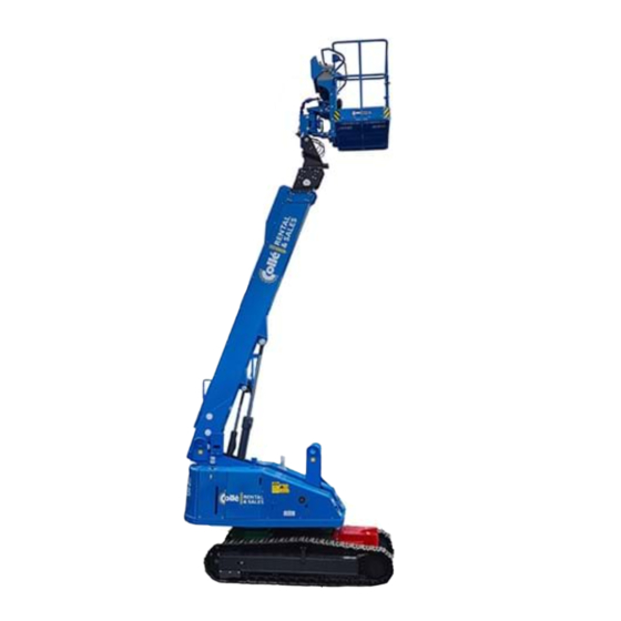
Part Names Part names SR12C SR14CJ (7) (8) (9) (10) (11) (12) (13) (14) (15) (13) (14) (15) (27) (26) (25) (24) (23) (22) (21) (20) (19) (18) (16) (18) (17) (16) M085H101 fi g. 4‒1 (1) Engine (17) Fly Jib (If equipped) (2) Rotation Lock Pin (18) Platform Leveling Cylinder, Upper... -
Page 24: Upper Controls
(6) Work Light Switch (Option) Upper Controls Turn on this switch and the (1) (2) (5) (6) (7) (8) (10) (11) work light will light on. (7) Head Light Switch (Option) Turn on this switch and the head light will light on. (8) Not used (9) Not used (10) Engine Start Switch / Emergency Pump Switch • Operate this switch up without pressing the foot switch and the engine will start. (18) (17) (16) (15) (14) (13) (12) • Hold this switch down to operate the machine with (19)(20) (21) (22) - Page 25 The foot switch is canceled if any of boom, (19) Not used fl y jib (if equipped), platform and traveling (20) System Failure Light function is not operated more than 20 seconds after depressing the foot switch, This light will go on or blink then the power indicator light blinks. in the event of a computer Release the switch once and the power control system failure. indicator light turns on, then operate again CAUTION to enable the functions. Stop using the machine and contact AICHI or AICHIʼs dealer for inspections, if this light goes on or blinks. (21) Fuel Level Light This light will go on when the fuel level is low. Refi ll the fuel. (22) Engine Failure Light This light will go on in the event of an engine failure, e.g., failed charging system, abnormally low oil pressure, and abnormally high cooling water temperature. Check the indicator lights on the lower controls to identify the cause. (23) Power Indicator Light This light will go on when ...
-
Page 26: Lower Controls
(7) Platform Level Adjust Switch Lower Controls Operate this switch up and the platform level will tilt up. Operate this switch down and the platform level will tilt down. (8) Pre-start Check Switch Follow the instruction and hold this switch up when the pre-start check is performed. (10) (9) Not use (11) (10) Rotating Beacon Switch (12) (Option) (17) (13) Turn on this switch and the (16) rotating beacon will light on. (11) Not use (15) (14) (12) Function Speed Select Switch (18)(19) (20) (21) (22) • Select “RABBIT” for a high speed function. • Select “TURTLE” for a low speed function. - Page 27 (27) Preheat Light the machine tilts more than This light goes on when max. allowable tilt angle. the key switch is turned to (22) System Failure Light “LOWER CONTROL” or “UPPER This light goes on or blinks CONTROL” and goes off when in the event of a computer the preheating is completed. control system failure. CAUTION Stop using the machine and contact AICHI or AICHIʼs dealer for inspections, if this light goes on or blinks. (23) Air Filter Clog Light This light goes on when the air fi lter is clogged. If this light goes on while the engine is in motion, clean or replace the air fi lter element. (24) Charge Light After starting the engine, this light goes off . If this light goes on while the engine is in motion, check the charging system, e.g. alternator and fan belt.
-
Page 28: Workplace Check
Workplace Check WARNING Do not move the machine to the workplace until the workplace check is performed. • Make sure to check the workplace before starting operation. Make sure there are no following hazards: ‒ near electric power lines and apparatus ‒ drop-off s or holes ‒ sloped surfaces ‒ slippery or icy surfaces ‒ inadequate surface support to withstand all load forces imposed by the machine ‒ bumps and fl oor obstructions ‒ curbs ‒ debris ‒ overhead obstructions ‒ hazardous locations ‒ wind and weather conditions ‒ presence of unauthorized persons ‒ other possible unsafe conditions • Remove the hazards, if any, after the workplace check. If it is not possible to remove them, do not move the machine to the workplace. • The machine can be used only on surfaces which are fi rm and for which all 4 wheels can maintain contact evenly with the ground. -
Page 29: Pre-Start Checks
Pre-Start Checks WARNING Make sure all decals are in place, legible and • Do not operate the machine before pre- no damage. Replace any lost or damaged decals. Use mild soap and water to clean the start checks described in this manual. decals if dirty. Refer to section 2 of chapter 2 • Perform the pre-start checks on fi rm, for decals and their locations. level surface. Begin the checks with the platform lowered. Check the fuel, engine oil, coolant, and • If the pre-start checks reveal any hydraulic oil levels. (Refer to chapter 7 for abnormalities, put an “Out of Order” details) sign on the machine, and have it repaired immediately at the nearest designated service agent. If you use the Check for cracks, or breaks in the boom, platform, and other parts. Check for loose machine without repairing it, it may bolts, and open covers. Check all the cause a serious accident. guardrails are attached properly. • If there is damage, such as cracks, on the welds of the platform guardrail, or on the guardrail pipes, change the Check that greasing points are lubricated suffi... -
Page 30: Lower Controls Check
‒ Emergency pump: Make sure that the boom can be operated while the Make sure that all compartment covers are in emergency pump is being operated. place and latched. Check that no oil is leaking from the Set up the machine in the following state: hydraulic components, hoses and pipes. ‒ Put the machine on a fi rm, level surface. ‒ Platform position: center Check the boom telescoping wire ropes for ‒ Platform load: 0 kg any damages. ‒ Fly jib angle: horizontal (if equipped) ‒ No wobble or unsteady movements when ‒ Boom elevation: minimum telescoping the boom. ‒ Boom rotation: rear center ‒ No damage at the wire rope ends. 2‒2 Lower Controls Check Leave the machine for a few minutes with Do the checks fi rst with the lower controls, the boom fully extended, and fully raised. then with the upper controls. Check visually that the boom does not descend on its own. Turn the key switch to “LOWER CONTROL” 2‒3 Upper Controls Check and make sure that the alarm buzzer sounds ... -
Page 31: Tilt Warning Check
If no abnormalities are revealed in steps 1〜21, check the following using the upper controls: DANGER • Retract the boom fully and raise the boom to the horizontal before checking. • Close and lock the doors of the covers securely before operating. Doors opening suddenly through the movements of the machine is hazardous. 2‒4 Tilt Warning Check Retract the boom fully and raise the boom to the horizontal. Raise the fl y jib to the horizontal. (if equipped) Make sure the tilt light goes on and alarm buzzer sounds when the machine tilts more than 5 ° , e.g. by traveling up onto a slope more than 5 ° (within the gradeability). 2‒5 Limited Travel Speed Check (1) Put the machine on a fi rm, level surface. (2) Extract the boom approx. 1 m and lower the boom below the horizontal. (3) Select the travel speed select switch to “HIGH SPEED” and attempt to travel at high ... -
Page 32: Maintenance
Maintenance Storage Method Diesel Fuel Specifi cation Location ASTM D975 After each use, store the machine as follows: No. 1D S15, S500 (1) Park the machine on a fi rm, level surface. No. 2D S15, S500 (2) Take all tools and materials from the EN590:96 European Union platform. ISO 8217 DMX International BS 2869-A1 or A2 United Kingdom (3) Retract and lower the boom fully. JIS K2204 Grade No.2 Japan (4) Shut down the engine by turning off the KSM-2610 Korea key switch, remove the key to prevent GB252 China using the machine without permission, table 7‒1 and store it suitably. (5) Chock the wheels. 2‒2 ... -
Page 33: Check The Battery Fluid Level
2‒3 Check the Battery Fluid Level (2) Make sure the engine and all systems are turned off and the emergency stop WARNING buttons are depressed. (3) Remove dipstick (fi g. 7‒3, 1) and wipe with The battery fl uid contains corrosive clean cloth. acid. When dealing with the battery, always wear appropriate protective clothing and equipment to protect your hands, eyes, face and body, and avoid contacting battery fl uid. (1) Check the battery fl uid levels every day (especially when using the machine in warm and dry climates). M085U332 (2) When the battery fl uid level has dropped fi g. 7‒3 more than 10 mm, add only distilled water (4) Fully reinsert dipstick. until the battery fl uid level is 2 mm below (5) Remove dipstick. The oil level should be the bottom of the fi... -
Page 34: Periodic Maintenance
• Perform a monthly and annual inspection referring to the separate service manual. (1) Make sure the machine is level. ‒ Depending on the laws of the country in (2) Make sure the engine and all systems which the machine is being used, keep are turned off and the emergency stop the records of the checks for the required buttons are depressed. number of years. (3) Check the level of engine coolant in the ‒ For any doubts you may have about reserve tank (fi g. 7‒5, 1). When the engine handling, inspection or spare parts, is cold, the coolant level in the tank should contact AICHI or AICHIʼs dealer. be at or slightly above the “LOW” (COLD) ‒ Refer to the separate service manual for mark (fi g. 7‒5, 2) on the coolant reserve what must be checked regularly. tank. If the coolant level is at the “FULL” (HOT) mark (fi g. 7‒5, 3) when the engine • If the machine has not been used for over is cold, the coolant will expand when it one month, make sure to perform the becomes hot and possibly spray out of the monthly inspection before use. overfl ow hose. 3‒2 Crawler Tracks As slack will form on the crawler tracks due ... -
Page 35: Adjustment Interval
Set the boom stand (fi g. 7‒6, B) and the A grease fi tting (fi g. 7‒8, A) is located on wood block (fi g. 7‒6, A) to prop up the fi rst the right and left sides of the chassis frame. boom end. Use the wood block that is wider Supply grease to the grease cylinder through than the width of fi rst boom end. the grease fi tting to adjust the tension of the track. Adjust the tension of the track so that Avoid the tie-down ring (fi g. 7‒6, C), and there is 115〜125 mm of slack between the center the fi rst boom end on the wood chassis frame and track link. (fi g. 7‒9) block. Make sure the stand is stable. M085K401 fi g. 7‒8 M085K102 Chassis frame fi g. 7‒6 Track roller WARNING Fixate the stand with brace members so that the stand does not fall over during ... -
Page 36: Engine Maintenance
Cooling Check and Refi ll ○ System Engine Coolant Electrical Check Indicators ○ Equipment Check Engine Oil ○ Level Drain and Fill ◇ Engine Oil ◇ Engine Oil 2nd 1st and Replace Engine time after Oil Filter Check and Refi ll ○ Fuel Tank Level Fuel Check Fuel Filter ○ / Water Separator table 7‒4 NOTICE Contact AICHI or AICHIʼs dealer for the maintenance items other than the table above. -
Page 37: Operation
Operation (a) Charge light NOTICE After starting the engine, the charge light goes off . The motion alarm buzzer sounds when If the light goes on whilst the machine is in motion to warn the the engine is in motion, it is people nearby. because of a charging system failure Starting the Engine (b) Oil pressure light After starting the engine, 1‒1 Starting from Ground the oil pressure light goes Do the following to start the engine from the off . If the light goes on lower control panel. whilst the engine is in motion, it is because of an Turn the key switch to “LOWER engine lubrication system failure. CONTROL,” and then, make sure If this light goes on whilst the engine is that both of the oil pressure and in motion, check the engine lubrication charge lights go on. system, e.g., shortage or leakage of Air Cleaner Clog Light engine oil or oil fi... - Page 38 NOTICE Before operating the machine for the fi rst time at the start of work, or during checks, make sure that the rotation lock pin is unlocked. (See fi g. 8‒2) Engine Start Switch Pre-heat Light M082L622 fi g. 8‒5 NOTICE • Do not hold the engine start switch up for 15 seconds or more. Failure to release your hand could result in damage to the starter motor. • Take the interval of 30 seconds or more Rotation is locked Unlocked before re-starting the engine to prevent M0858121 damaging the engine. fi g. 8‒2 If the engine does not start easily Make sure both of the upper and lower because of the cold, start the emergency stop button are pulled out to engine after the pre-heat light “ON.” has gone off . Emergency Stop Button After starting engine, idle the engine for about 5 minutes for warming up.
-
Page 39: Starting From Platform
Engine Start Switch M085F321 fi g. 8‒7 Fuel Level Light M082L722 fi g. 8‒6 NOTICE NOTICE • Do not hold the engine start switch up for 15 seconds or more. Failure The capacity of the fuel tank is 120 liters. to release your hand could result in 1‒2 Starting from Platform damage to the starter motor. Do the following to start the engine from the • Take the interval of 30 seconds or more upper controls. before re-starting the engine to prevent damaging the engine. Turn the key switch to “UPPER CONTROL,” and then, make sure After starting engine, idle the engine for the engine failure light goes on. about 5 minutes for warming up. NOTICE NOTICE • Engine failure light If the outside air temperature is below After the engine starts, the temperature range for the hydraulic ... -
Page 40: Stopping The Engine
Stopping the Engine Push in either of the upper or lower emergency stop button to “OFF,” or turn the key switch to “OFF” to stop all functions and turn the engine off . Emergency Stop Button M082Q330 fi g. 8‒12 M085M221 WARNING fi g. 8‒9 Emergency Stop Button • Do your work while standing fi rmly on the platform. If your feet separate from the platform, by climbing on the guardrails, e.g., there is a possibility you will lose your balance, and fall. M082M323 • Before rotating the boom, make sure fi g. 8‒10 that no person or obstacle is around the turntable. If the boom cannot be raised and the rear of the turntable cannot be seen, have a guide to assist you. CAUTION Key Switch • Before operation, make sure the M082L423 fi g. 8‒11 platform is level. -
Page 41: Foot Switch
NOTICE WARNING When painting, make sure to close the • If the turntable has been rotated 180° , cover of the upper control panel after the traveling direction will be opposite the platform has been put in position, to the lever movements, so be careful. and keep the decal clean. Make sure to check the direction of the arrow on the decal and on the chassis 3‒1 Foot Switch when traveling. WARNING Forward (Green) Do not disable the foot switch in any way e.g. by binding. Backward (Red) Forward Backward (Green) (Red) M085D121 fi g. 8‒15 • Before traveling, make sure that no Foot Switch person or obstacle is in the traveling direction. M082Q221 fi g. 8‒13 CAUTION Except for those listed here, you must ... -
Page 42: Travel Speed Select
• When traveling, make sure there is Travel Speed Select Switch enough distance between the traveling surface and bottom of the platform, or the tip of the boom. If there is not enough distance, depending on the unevenness of the traveling surface, the bottom of the platform or the tip of the boom may come in contact with the traveling surface, and may be damaged. Travel control lever (Left) In particular, if the fl y jib is attached, Travel control lever (Right) M085F521 fully raise the fl y jib before traveling. fi g. 8‒16 3‒2‒1 Travel Speed Select 3‒2‒2 Forward and Backward DANGER Depress the foot switch and operate both the travel control levers to the traveling direction. Steer straight while traveling at high speeds. Switch to “LOW SPEED” before turning. The platform will swing widely, and there is a possibility the operator will be thrown from the platform. CAUTION • Do high-speed traveling only when the M085B101 traveling surface is fl... -
Page 43: Spin Turn
(2) Forward / Backward right turns 850 mm M0863201 fi g. 8‒21 NOTICE M085B301 • Before rotating the boom, make sure fi g. 8‒19 the rotation lock pin has been unlocked. NOTICE • The boom may not rotate smoothly when the machine tilts. If the direction of travel cannot be Use the three control levers for the boom changed due to road surface conditions, elevation, telescope and rotation to operate fi rst adjust the position of the machine the boom. by traveling forward or backward, then And use the fl y jib switch to operate the fl y jib change course. elevation. (If equipped) Boom Rotation Boom Elevation 3‒2‒4 Spin Turn Control Lever Control Lever Depress the foot switch and operate the travel control levers as shown in the fi gure below to make the CW (clockwise) or CCW spin turn ... -
Page 44: Platform Rotating Operation
3‒4 Platform Rotating Operation CAUTION CAUTION If the system failure light blinks, there is a problem with the electrical system. • Keep the platform straight while Quickly and fully retract the boom, stop traveling. the operation, and have the machine • Before rotating the platform, stop the checked immediately. machine movement and make sure that System Failure Light no person or obstacle is around the machine. Depress the foot switch and operate the platform rotation switch to rotate the platform. Platform Rotation Switch M085F621 fi g. 8‒25 Lower Controls (from ground) M085F820 CAUTION fi g. 8‒23 • Do not push the boom or platform to 3‒5 Horn Operation the ground, or use them to crash into Use the horn button. -
Page 45: Boom Operation
Boom Rotation Switch electrical system. Enable Switch Boom Telescope Switch System Failure Light M082L322 M082K122 fi g. 8‒29 fi g. 8‒27 WARNING 4‒2‒1 Boom Elevating Hold the enable switch up to “ON” and Stop using the machine and contact operate the boom elevation switch to raise or AICHI or AICHIʼs dealer for inspections, if lower the boom. this light goes on or blinks. Immediately, 4‒2‒2 Boom Rotating retract and lower the boom fully, stop Hold the enable switch up to “ON” and the operation, and have the machine operate the boom rotation switch to rotate the checked. boom. NOTICE 4‒2‒3 Boom Telescoping This light also blinks when the machine Hold the enable switch up to “ON” and tilts excessively, but this is not a failure. -
Page 46: Platform Leveling System
Platform Leveling System DANGER 5‒1 Platform Level Adjustment Do not allow any person or object on If the pre-start check reveals that the platform the platform when bleeding air. Use is tilted (front-back tilt of about 3° or more), lower control panel to bleed air from adjust it as follows. the platform leveling system. Platform Level Adjust Switch Put the machine on a fi rm, level surface. Move the boom to a position where it is easy to adjust. Hold the enable switch up to “ON”. Operate M085FA20 the platform level adjust switch on the lower fi g. 8‒30 controls to fully tilt the platform forward and backward several times. Platform Level Adjust Switch Platform Level Adjust Switch Enable Switch M082L822 fi g. 8‒31 Enable Switch M082L822 fi g. 8‒32 NOTICE ... -
Page 47: Emergency Operation
Emergency Operation Emergency Lowering NOTICE If the engine or main pump fails, If the emergency operation was done use the emergency pump to because of a malfunction, immediately lower the platform. stop the operation, and have the NOTICE machine checked and repaired. • Operate the emergency pump every Emergency Stop other 30 seconds. The continuous Use the emergency stop button. operation in excess of 30 seconds may When this button is pushed in, cause the damaged emergency pump. the engine stops and all of the functions are disabled. Push in the emergency stop button in the following cases; (1) When a person in the platform stops all of the machine movements to avoid hazards. (2) When a person on the ground judges that 30 seconds 30 seconds 30 seconds 30 seconds the operation from the platform is unsafe. or less or more or less or more (3) ... -
Page 48: Lower Controls (From Ground)
NOTICE When the upper or lower emergency stop button is pushed in or the key switch is turned to “LOWER CONTROL,” operating with the emergency pump from the upper control is not possible. Pull out the emergency stop button to “ON.” Depress the foot switch. Hold the emergency pump switch down, and activate each function at the same time. The emergency pump will turn on when both the emergency pump switch and the operation switch are turned on. 2‒2 Lower Controls (from ground) Emergency Pump Switch M082L222 fi g. 9‒5 Turn the key switch to “UPPER CONTROL” or “LOWER CONTROL.” Pull out the emergency stop button to “ON.” Hold the emergency pump switch down, and activate each function at the same time. The emergency pump will turn on when both the emergency pump switch and the operation switch are turned on. -
Page 49: Transporting
Transporting • Use a winch for loading/unloading, if NOTICE the ramp is too steep or slippery. • Failure to avoid these fall hazards could • This information about transporting is result in death or serious injury. off ered as a recommendation. • Only the qualifi ed persons shall operate the transport vehicle, crane, forklift, and Park the transport vehicle on a fi rm, level the machine. surface. • All persons on transportation must comply with employer, work area, and Chock the wheels of the transport vehicle. local and national safety regulations regarding the use of these machinery. Lock the turntable with the turntable lock • Each machinery must comply with all pin and prevent the turntable from being applicable regulations, and must be rotated during the transportation. inspected and used in accordance with their manufacturerʼs instructions. WARNING Make sure the transport vehicle capacity, crane capacity, loading ... -
Page 50: Tie Down
Tie Down NOTICE Do not tighten the tie down chains Tie down the chassis or wire ropes marked “※” too much. of the machine to the Tighten them just so that the platform transport vehicle bed is not swung or bounced during the securely. Place pads on transportation. the crawler tracks to protect it. (fi g. 10‒2, A) Hoisting the Machine WARNING • Do not allow any person to get under the machine while hoisting. • Do not pass the sling chains or wire ropes except designated rings. • Failure to heed warnings could result in breaking, falling, or other hazards leading to death or serious injury. Retract and lower the boom fully, and position the fl y jib to horizontal if equipped. M0858203 fi g. 10‒2 Pass the sling chains or wire ropes through the hoisting rings located on the turntable as ... -
Page 51: Hoisting With Boom Raised
Hoisting with Boom Raised When you are working in a cramped location, you may not have enough room to lower the boom prior to hoisting. In such cases, it is permissible to hoist the machine while the boom is still up. Proceed as follows. • Sling chains or wire ropes used for hoisting should be at least 10 meters long. • Set the boom angle to 60° or lower (that is, at least 10° below the maximum raise angle of 70° ). • If sling chains or wire ropes contact the boom, place pads on the boom to protect it. * This figure shows the gravity center at the boom angle of 60 degrees. Pads 60° 1680 mm M0858500... -
Page 52: Storage
Storage (1) Clean all part of the machine. NOTICE • Do not use high-pressure washing. • If working in winter, be careful to avoid ice formation. • Rusting may occur if antirust oil is not applied. (4) Store the machine in a dry indoor area. If it is necessary to store the machine out of doors, park it in a fl at area. M0859300 fi g. 11‒1 (2) Lubricate in accordance with the lubrication instructions. (3) If storing for a long period of time, proceed as follows. ‒ Coat the cylinder rods with a suffi cient quantity of antirust oil. ‒ Start the engine and check operation once every month, so as to ensure that the oil M0859500 fi lm on lubricated parts remains intact. fi g. 11‒3 ‒ Before checking the operation, remove the (5) Periodically operate the boom, so as to coating of antirust oil from the oil cylinder ... -
Page 53: Specifi Cations
190 L 39 ~ 51 s / -7 ~ 70 ° Elevation Down 39 ~ 51 s / -7 ~ 70 ° 24 ~ 36 s / 6.05 m Telescope 19 ~ 31 s / 6.05 m Turntable Rotation (Stowed) 120 ~ 150 s / 360 ° ‒ 20 ~ 30 s / -70 ~ 60 ° Fly Jib Elevation Down ‒ 15 ~ 25 s / -70 ~ 60 ° Platform Rotation 10 ~ 20 s / -90 ~ 90 ° Max. Travel Speed Stowed 2.6 km/h Elevated 0.8 km/h (Level Surface) * The machine is designed for both indoor and outdoor use. * For the allowance which is not specifi ed otherwise is in accordance with AICHIʼs own standards. * Function speeds and gradeability assume there is 1 person on the machine. * Travel speed and gradeability depends on the condition of the traveling surface. * Specifi cation is approximate and does not incorporate diff erent option confi gurations. * Advisable atmospheric temperature range: -20 ℃ ~ +40 ℃... -
Page 54: Work Range Diagram
Work Range Diagram 2‒1 SR12C 2‒2 SR14CJ Rated load: 250 kg (6 ft platform) Rated load: 250 kg (6 ft platform) 227 kg (8 ft platform) 227 kg (8 ft platform) 360° 360° 14 [m] 14 [m] M085J120 M085J220 fi g. 12‒1 fi g. 12‒2 1. The boom defl ection is not taken into account in the above working range diagram. 2. The working range is the same in any boom-rotated directions. 3. The working range indicated in the graph is a reference measured on level fi rm ground. 4. The counter weight should be attached to the specifi ed point.
Need help?
Do you have a question about the SR12C and is the answer not in the manual?
Questions and answers