Table of Contents
Advertisement
Quick Links
M-14-22
JULY 2015
To fi nd maintenance & parts information for your
BMR-CS Liftgate, go to www.maxonlift.com. Click
the PRODUCTS, COLUMNLIFT & BMR-CS buttons.
Open the Maintenance Manual in the PRODUCT
DOCUMENTATION window.
Operation Manual Contains:
• Warnings
• Decal & Plate Locations
• Standard Control Locations
• Liftgate & Retention Ramp Operation
© MAXON Lift Corp. 2015
Advertisement
Table of Contents

Related Manuals for Maxon BMR-CS Series


Summary of Contents for Maxon BMR-CS Series
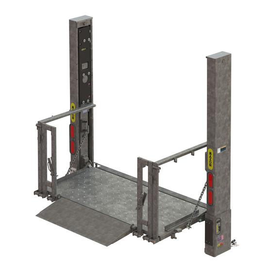
- Page 1 • Liftgate & Retention Ramp Operation To fi nd maintenance & parts information for your BMR-CS Liftgate, go to www.maxonlift.com. Click the PRODUCTS, COLUMNLIFT & BMR-CS buttons. Open the Maintenance Manual in the PRODUCT DOCUMENTATION window. © MAXON Lift Corp. 2015...
-
Page 3: Table Of Contents
TABLE OF CONTENTS WARNINGS ................5 DECALS & PLATES ..............6 STANDARD CONTROL LOCATIONS ........8 POWER DOWN CONTROLS (IF EQUIPPED) ......9 PUMP BOX CONTROLS ............10 FORKLIFT ADVISORY ............11 LOADING VEHICLE ..............12 OPENING THE PLATFORM ............12 LOWERING THE PLATFORM ..........12 OPENING THE RETENTION RAMP - STEEL PLATFORM ..13 OPENING THE RETENTION RAMP - ALUMINIUM PLATFORM ................14 POSITIONING LOAD ...............15... - Page 4 STOW RETENTION RAMP ............23 STOW PLATFORM ..............24 DOCK LOADING & UNLOADING ...........26 LOWER PLATFORM BELOW DOCK LEVEL......26...
-
Page 5: Warnings
5. Comply with all attached instruction decals and warning decals. 6. Keep decals clean and legible. If decals are illegible or missing, have them replaced. Get free replacement decals from Maxon. 7. Never drive a forklift on the Liftgate platform. -
Page 6: Decals & Plates
DECALS & PLATES NOTE: Ensure there is no residue, dirt, or corrosion where decals are attached. If necessary, clean surface before attaching decals. NOTE: Preferred decal layout is shown. De- cals on the Liftgate are attached at the factory. If vehicle does not permit this layout, decals in the manual and de- cal kit must be applied so that they are easily visible when approaching vehi-... - Page 7 (REFER TO TABLE 7-1) DECAL SHEET FIG. 7-1 MODEL ORDER P/N DECAL “C” BMR-35-CS 289163-01 3500 LBS. [1600 KG] BMR-44-CS 289163-02 4400 LBS. [2000 KG] DECAL SHEET PART NUMBERS TABLE 7-1...
-
Page 8: Standard Control Locations
STANDARD CONTROL LOCATIONS GROUND ACCESS - COLUMN SWITCH Toggle switches on column switch (FIG. 8-1A) let operator raise (UP), lower (DOWN), FOLD, and UNFOLD the platform (FIG. 8-1) while standing on the ground. FIG. 8-1A FIG. 8-1 PLATFORM ACCESS - RUNNER SWITCH Toggle switch (FIG. -
Page 9: Power Down Controls (If Equipped)
POWER DOWN CONTROLS (IF EQUIPPED) GROUND ACCESS - COLUMN SWITCH POWER DOWN button (if equipped) on column switch (FIG. 9-1A) lets operator lower platform by pressing the POWER DOWN button once and pushing and holding the toggle switch (DOWN) (FIG. 9-1), while standing on the ground. -
Page 10: Pump Box Controls
PUMP BOX CONTROLS MASTER SELECT SWITCH The master select switch (FIGS. 10-1B, 10-2B and 10-2C) applies or removes battery power from the pump(s). For a single pump box (FIGS. 10-1A and 10-1B), turn the MASTER SELECT SWITCH to 1 to operate Liftgate. -
Page 11: Forklift Advisory
FORKLIFT ADVISORY WARNING Keep forklift OFF of platform. FIG. 11-1 FIG. 11-2... -
Page 12: Loading Vehicle
LOADING VEHICLE OPENING THE PLATFORM NOTE: The 2 platform fl ashing lights are fl ashing when platform is unfolding and unfolded. The lights stop fl ashing when the platform is folded/stowed. Push toggle switch to DOWN position (FIG. 12-1) to lower platform until runner arrow and yellow tape are about even (FIG. -
Page 13: Opening The Retention Ramp - Steel Platform
OPENING THE RETENTION RAMP - STEEL PLATFORM To release retention ramp, rotate locks in direction of arrows (FIG. 13-1) and unfold ramp to the ground (FIG. 13-2). LOCK RAMP IN RETENTION POSITION LOCK FIG. 13-1 RAMP POSITION FIG. 13-2... - Page 14 LOADING VEHICLE - Continued OPENING THE RETENTION RAMP - ALUMINIUM PLATFORM To unfold retention ramp, fi rst push down on retention ramp (FIG. 14-1A) to release tension on lock. Next, push down on lock mechanism (FIG. 14-1B) and lift the retension ramp until it is in the ramp position (FIG. 14-1C). RAMP POSITION RAMP...
-
Page 15: Positioning Load
POSITIONING LOAD WARNING A load should never extend past the edges of the platform. Do not place unstable loads on platform and do not allow load to exceed lifting capacity of Liftgate. If standing on platform, do not allow your feet to extend beyond inboard edge of platform. -
Page 16: Raising & Unloading Platform - Steel
LOADING VEHICLE - Continued RAISING & UNLOADING PLATFORM CAUTION A ramp in retention position can trip you when stepping over it. To prevent possible injury, get on the platform before putting the ramp in retention position. RETENTION POSITION LOCK LOCK 1. - Page 17 CHAIN 2. Use runner switch to raise (UP) PLATFORM platform from ground level to RAILING bed height (FIG. 17-1). Release switch when platform reaches CHAIN bed height. HOOK 3. Unhook chain from platform railing as shown in FIG. 17- 1A. Carefully move the load into vehicle (FIG.
-
Page 18: Unloading Vehicle
UNLOADING VEHICLE OPENING THE PLATFORM Push column UP/DOWN toggle switch to DOWN position (FIG. 18-1) to lower platform (FIG. 18-2A) until runner arrow and column decal are about even (FIG. 18-2B). Platform will be released from the locking wedges on the Liftgate column. -
Page 19: Raising The Platform
RAISING THE PLATFORM Use runner switch to raise platform (FIG. 19-1) from ground level to bed height. Release switch when platform reaches bed height. RUNNER SWITCH INBOARD EDGE FIG. 19-1... -
Page 20: Positioning Load
UNLOADING VEHICLE - Continued POSITIONING LOAD WARNING A load should never extend past the edges of the platform. Do not place unstable loads on platform and do not allow load to exceed lifting capacity of Liftgate. Load must not exceed maximum of 3 cylinders on each side of platform within the rated Liftgate capacity. -
Page 21: Lowering & Unloading Platform
LOWERING & UNLOADING PLATFORM WARNING Before lowering platform, make sure area surrounding platform is clear of people and objects. If standing on platform, do not allow your feet to extend beyond inboard edge of platform. 1. Use runner switch to lower platform to the ground (FIG. - Page 22 LOWERING & UNLOADING PLATFORM - Continued 3. Unhook chain from platform railing (FIG. 22-2A). PLATFORM CHAIN RAILING HOOK 4. Carefully move load off platform (FIG. 22-2) and then move it to a place where it will not become CHAIN a hazard for people and other vehicles.
-
Page 23: Stowing Platform
STOWING PLATFORM STOW RETENTION RAMP STEEL PLATFORM Fold ramp to stowed position (FIG. 23-1B) as STOWED shown in FIGS. 23-1A & POSITION 23-1B. RAMP POSITION FIG. 23-1B FIG. 23-1A ALUMINUM PLATFORM Push ramp to stowed STOWED position until it locks, as POSITION shown in FIG. -
Page 24: Stow Platform
STOWING PLATFORM - Continued STOW PLATFORM CAUTION Platform and bottom stops could be damaged if platform is folded with heel below the column bottom stops. Bottom stops will interfere with folded platform being raised to up position. Prevent damage by aligning arrow decals on column & runner before fold- ing platform. - Page 25 WARNING Upper locking wedges must be engaged before moving vehicle. 3. Use column switch to raise (UP) platform to upper locking position as follows (FIG. 25-1A). Raise platform until round wedge on each opener arm is behind the upper locking wedge on each column (FIGS.
-
Page 26: Dock Loading & Unloading
DOCK LOADING & UNLOADING LOWER PLATFORM BELOW DOCK LEVEL CAUTION Use dock plate for moving loads between dock and vehicle. Dock plate must be supported by dock and vehicle fl oor. It must not rest on Liftgate platform. NOTE: Lower the platform and plat- form railing before backing vehicle to dock. - Page 27 2. Remove pin (FIG. 27-1A) on each side of platform to unlock platform railing. Lower the railing until it hangs over the platform as shown in FIG. 27-1B. FIG. 27-1A FIG. 27-1B CAUTION To prevent damage to Liftgate, use dock plate for moving loads between dock and vehicle.
- Page 28 LOWER PLATFORM BELOW DOCK LEVEL - Continued 4. When fi nished loading and unloading from the dock, raise platform railing on each side of platform as shown in FIG. 28-1A. Pin platform railing to platform as shown in FIG. 28-1B. FIG.
- Page 29 WARNING Upper locking wedges must be engaged before moving vehicle. 5. Use column switch to raise (UP) platform to upper locking position as follows (FIG. 29-2A). Raise platform until round wedge on each opener arm is behind the upper locking wedge on each column (FIGS.
Need help?
Do you have a question about the BMR-CS Series and is the answer not in the manual?
Questions and answers