Table of Contents
Advertisement
Quick Links
Advertisement
Table of Contents

Related Manuals for C&T Solution VCO-6131E-4M2


Summary of Contents for C&T Solution VCO-6131E-4M2
- Page 1 VCO-6131E-4M2 Superior Fanless Embedded System...
-
Page 2: Table Of Contents
VCO-6131E-4M2 l User’s Manual Table of Contents Prefaces ……………………………………………………………………………………………….. 04 Revision ………………………………………………………..……………………………..……………….……….. 04 Disclaimer ……………………………………………………….…….……………….………………….………….. Copyright Notice …………………………………….…….….………………………………….………………… Trademarks Acknowledgment …………..………….………………………………………....Environmental Protection Announcement ……………………………………..……..……………….. Safety Precautions ……………………………………………………………………………………….….…….. Technical Support and Assistance ………………………………...……………………..…….…….……. Conventions Used in this Manual …………………………………..……………………..….……….. Package Contents ……………………………………………………………………..…..…………………….…... - Page 3 VCO-6131E-4M2 l User’s Manual Chapter 4 BIOS Setup …………………………………………..……………..……………… 88 BIOS Introduction …….……….……………………………………….…….…..….…………... 89 Main Setup ……..……….………………….…………………………..….….………………..90 Advanced Setup …………………………………………..………………………………………… 91 4.3.1 CPU Configuration ..…………...………………………………………..………………. 92 4.3.2 PCH-FW Configuration ……..……………….………..………..……………..……... 93 4.3.3 SATA And RST Configuration ………………..……………….………………..…..94 4.3.4 RST (UEFI RAID) Configuration ……………………………………….…………..95 4.3.5 Trusted Computing ……………………………..……………….………………..…..
-
Page 4: Prefaces
VCO-6131E-4M2 l User’s Manual Prefaces Revision Revision Description Date Manual Released 2021/01/10 Disclaimer All specifications and information in this User’s Manual are believed to be accurate and up to date. C&T Solution Inc. does not guarantee that the contents herein are complete, true, accurate or non-misleading. -
Page 5: Safety Precautions
Preface VCO-6131E-4M2 l User’s Manual Safety Precautions Before installing and using the equipment, please read the following precautions: Put this equipment on a reliable surface during installation. Dropping it or letting it fall could cause damage. The power outlet shall be installed near the equipment and shall be easily accessible. -
Page 6: Technical Support And Assistance
Preface VCO-6131E-4M2 l User’s Manual Technical Support and Assistance 1. Visit the C&T Solution Inc website at www.candtsolution.com where you can find the latest information about the product. 2. Contact your distributor, our technical support team or sales representative for technical support if you need additional assistance. -
Page 7: Package Contents
Preface VCO-6131E-4M2 l User’s Manual Package Contents Before installation, please ensure all the items listed in the following table are included in the package. Item Description Q’ty VCO-6131-4M2 Series Fanless Embedded System Utility DVD Driver Wall Mount Kit Accessory Kit Ordering Information Model No. -
Page 8: Chapter 1 Product Introductions
Chapter 1 Product Introductions... -
Page 9: Overview
VCO-6131E-4M2 l User’s Manual Chapter 1: Product Introductions 1.1 Overview The GPU series adopts 9th Gen. Intel® Core™ i7-9700E (4.4GHz, 8 Cores) / i5-9700E (4.2GHz, 6 Cores) / i3-9100E (3.7GHz, 4 Core) / i7-9700TE (3.8GHz, 8 Cores) / i5-9500TE (3.6GHz, 6 Cores) / i3-9100TE (3.2GHz, 4 Cores) or 8th Gen. -
Page 10: Hardware Specification
VCO-6131E-4M2 l User’s Manual Chapter 1: Product Introductions 1.2 Hardware Specification System 2x RS-232/422/485, Support 8 Gen Intel® CFL-R S Processor 2x RS-232/422/485 (internal) (LGA 1151, 65W/35W TDP) 4x USB 3.2 Gen 2 (10 Gbps), Intel® Core™ i7-9700E, 8 Cores, 12MB cache, up to 4.4 GHz (24V) 5x USB 3.2 Gen 1 (5 Gbps, internal),... -
Page 11: System I/O
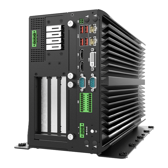
VCO-6131E-4M2 l User’s Manual Chapter 1: Product Introductions 1.3 System I/O Front Panel DisplayPort ATX power on/off switch Used to connect a DisplayPort monitor Press to power-on or power-off the system DVI-I port USB 3.2 Gen 2 port (10 Gbps) - Page 12 VCO-6131E-4M2 l User’s Manual Chapter 1: Product Introductions 1.3 System I/O Top Panel Universal I/O Bracket Used to customized I/O output Top Panel Rear Panel...
-
Page 13: Mechanical Dimension
VCO-6131E-4M2 l User’s Manual Chapter 1: Product Introductions 1.4 Mechanical Dimensions Unit: mm... -
Page 14: Chapter 2 Switches And Connectors
Chapter 2 Switches and Connectors... -
Page 15: Switch And Connector Locations
VCO-6131E-4M2 l User’s Manual Chapter 2: Switches and Connectors 2.1 Switch and Connector Locations 2.1.1 Top View... -
Page 16: Bottom View
VCO-6131E-4M2 l User’s Manual Chapter 2: Switches and Connectors 2.1.2 Bottom View PCIE2 PCIE1 SATA1 SATA3 LED4 LED3 SATA4 SATA2 SATA with Power Connector HDD_LED1 SIM2 PWR_LED1... -
Page 17: Connector / Switch Definition
VCO-6131E-4M2 l User’s Manual Chapter 2: Switches and Connectors 2.2 Connector / Switch Definition List of Connector / Switch Connector Location Definition AT_ATX1 AT / ATX Power Mode Switch PWR_SW1 Power Switch RESET1 Reset Switch USB 3.2 Gen 2 、 USB 3.2 Gen 1 、 USB2.0... -
Page 18: I/O Interface Descriptions
VCO-6131E-4M2 l User’s Manual Chapter 2: Switches and Connectors 2.3 I/O Interface Descriptions 2.3.1 LPC Debug Con Signal Signal +3.3V LPC_AD3 LPC_AD2 Reset LPC_AD1 LPC_FRAME-L LPC_AD0 Clock... - Page 19 VCO-6131E-4M2 l User’s Manual Chapter 2: Switches and Connectors 2.3 I/O Interface Descriptions 2.3.2 Power Con 1 2 3 4 POWER1 Signal +12V...
- Page 20 VCO-6131E-4M2 l User’s Manual Chapter 2: Switches and Connectors 2.3 I/O Interface Descriptions 2.3.3 DC IN/IGN IN (+9V ~ +48V) 1 2 3 DC_IN1 Signal +DC_IN IGN_SENSE...
- Page 21 VCO-6131E-4M2 l User’s Manual Chapter 2: Switches and Connectors 2.3 I/O Interface Descriptions 2.3.4 COM Con COM5_1 , COM6_1 Signal Signal DCD# DSR# RTS# CTS# DTR# RS232 / RS422 / RS485 Connector 2x5 10-pin box header, 2.0mm pitch RS232 Definition...
- Page 22 VCO-6131E-4M2 l User’s Manual Chapter 2: Switches and Connectors 2.3 I/O Interface Descriptions COM1_2 , COM3_4 RS232 / RS422 / RS485 Connector Type: 9-pin D-Sub RS422 / 485 Full Duplex RS232 Definition RS485 Half Duplex Definition Definition 1(10) DCD# DATA-...
- Page 23 VCO-6131E-4M2 l User’s Manual Chapter 2: Switches and Connectors 2.3 I/O Interface Descriptions 2.3.5 SF100 SPI Con Signal Signal Power ( 3V ) MISO MOSI SPI_GATE#...
- Page 24 VCO-6131E-4M2 l User’s Manual Chapter 2: Switches and Connectors 2.3 I/O Interface Descriptions Left Right AT_ATX1: AT / ATX Power Mode Switch Switch Definition 1-2 (Left) ATX Power Mode (Default) 2-3 (Right) AT Power Mode Left Right CAR_PWR1: PC / Car Mode Switch...
- Page 25 VCO-6131E-4M2 l User’s Manual Chapter 2: Switches and Connectors 2.3 I/O Interface Descriptions 1 2 3 DELAY_TIME1 Power off delay time setup Switch Switch 1 / 2 / 3 Definition ON / ON / ON 3 sec.(Default Shutdown Timer by O.S)...
- Page 26 VCO-6131E-4M2 l User’s Manual Chapter 2: Switches and Connectors 2.3 I/O Interface Descriptions LINE_OUT1 MIC_IN1 LINE_OUT1 : MIC_IN1 : Line-out Jack (Green) Connector Type: 5- Microphone Jack (Pink) Connector Type: pin Phone Jack 5-pin Phone Jack Definition Definition OUT_R MIC_R...
- Page 27 VCO-6131E-4M2 l User’s Manual Chapter 2: Switches and Connectors 2.3 I/O Interface Descriptions CLR_CMOS1: Clear BIOS Switch Switch Definition 1-2 (Left) Normal Status (Default) 2-3 (Right) Clear BIOS PWR_SW1: Power Button Definition Definition Power Button...
- Page 28 VCO-6131E-4M2 l User’s Manual Chapter 2: Switches and Connectors 2.3 I/O Interface Descriptions RESET1 : Reset Button Definition RESET USB3_1 : USB3.1 Connector, Type A Definition Definition USB3_RX+ USB2_D- USB2_D+ USB3_TX- USB3_TX+ USB3_RX-...
- Page 29 VCO-6131E-4M2 l User’s Manual Chapter 2: Switches and Connectors 2.3 I/O Interface Descriptions CN7 : USB2.0 Connector 2x5 10-pin box header, 2.0mm pitch Definition Definition USB2_D- USB2_D- USB2_D+ USB2_D+...
- Page 30 VCO-6131E-4M2 l User’s Manual Chapter 2: Switches and Connectors 2.3 I/O Interface Descriptions CN6 : USB3.1 Connector, Type A x 4 Definition Definition USB3_RX+ USB2_D- USB2_D+ USB3_TX- USB3_TX+ USB3_RX-...
- Page 31 VCO-6131E-4M2 l User’s Manual Chapter 2: Switches and Connectors 2.3 I/O Interface Descriptions SIM1 : Top size SIM Card Socket SIM2 : Bottom size SIM Card Socket SIM1 SIM2 Definition Definition UIM_PWR UIM_VPP UIM_RESET UIM_DATA UIM_CLK...
- Page 32 VCO-6131E-4M2 l User’s Manual Chapter 2: Switches and Connectors 2.3 I/O Interface Descriptions DVI_I1: DVI-I Connector Definition Definition DVI_TX2- DVI Hot Plug Detect DVI_TX2+ DVI_TX0- DVI_TX0+ VGA_DDC_CLOCK DVI_DDC_CLOCK VGA_DDC_DATA DVI_DDC_DATA VGA VSYNC DVI_TXCLK+ DVI_TX1- DVI_TXCLK- DVI_TX1+ VGA_RED VGA_GREEN VGA_BLUE VGA_HSYNC...
- Page 33 VCO-6131E-4M2 l User’s Manual Chapter 2: Switches and Connectors 2.3 I/O Interface Descriptions DP1 DP2 : Display Port Connector Definition Definition DP_LANE0_P DP_LANE3_N DP_LANE0_N DP_LANE1_P DP_AUX_P DP_LANE1_N DP_LANE2_P DP_AUX_N DP_HPD DP_LANE2_N DP_LANE3_P +3.3V...
- Page 34 VCO-6131E-4M2 l User’s Manual Chapter 2: Switches and Connectors 2.3 I/O Interface Descriptions DIO : Digital Input / Output Connector Type: Terminal Block 2x9 18-pin, 3.5mm pitch Definition Definition DIN1 DOUT1 DIN2 DOUT2 DIN3 DOUT3 DIN4 DOUT4 DIN5 DOUT5 DIN6...
- Page 35 VCO-6131E-4M2 l User’s Manual Chapter 2: Switches and Connectors 2.3 I/O Interface Descriptions Digital Input Wurung Digital Output Wurung...
- Page 36 VCO-6131E-4M2 l User’s Manual Chapter 2: Switches and Connectors 2.3 I/O Interface Descriptions PWR_SW2 : Remote Power Switch Type: Terminal Block 1x2 2-pin, 3.5mm pitch Definition Power Button...
- Page 37 VCO-6131E-4M2 l User’s Manual Chapter 2: Switches and Connectors 2.3 I/O Interface Descriptions PWR_SW3 : Remote Power Switch 1x4 pin box header, 2.0mm pitch Definition Power Button PWR_LED HDD_LED...
- Page 38 VCO-6131E-4M2 l User’s Manual Chapter 2: Switches and Connectors 2.3 I/O Interface Descriptions CN3 CN4 : LAN and USB3.1 GEN 2 Ports Connector Type:RJ45 port with LEDs and dual USB3.1 ports Definition Definition Definition LAN1_MDI0P USB2_D1- USB2_D2- LAN1_MDI0N USB2_D1+ USB2_D2+...
- Page 39 VCO-6131E-4M2 l User’s Manual Chapter 2: Switches and Connectors 2.3 I/O Interface Descriptions Act LED Status Definition Blinking Yellow Data Activity No Activity Link LED Status Definition Steady Orange 1Gbps Network Link Steady Green 100Mbps Network Link 10Mbps Network Link...
- Page 40 VCO-6131E-4M2 l User’s Manual Chapter 2: Switches and Connectors 2.3 I/O Interface Descriptions MINIPCIE2 : Mini PCI-Express Socket Definition Definition WAKE# +3.3V +1.5V CLKREQ# UIM_PWR UIM_DATA REFCLK- UIM_CLK REFCLK+ UIM_RST UIM_VPP RESET# +3.3VAUX +1.5V SMB_CLK SMB_DATA USB2_D- USB2_D+ +3.3V +3.3V +1.5V...
- Page 41 VCO-6131E-4M2 l User’s Manual Chapter 2: Switches and Connectors 2.3 I/O Interface Descriptions MINIPCIE1 : Mini PCI-Express / mSATA Socket Definition Definition WAKE# +3.3V +1.5V CLKREQ# UIM_PWR UIM_DATA REFCLK- UIM_CLK REFCLK+ UIM_RST UIM_VPP RESET# +3.3VAUX +1.5V SMB_CLK SMB_DATA USB2_D- USB2_D+ +3.3V...
- Page 42 VCO-6131E-4M2 l User’s Manual Chapter 2: Switches and Connectors 2.3 I/O Interface Descriptions SATA with Power Connector Definition Definition +12V DEVSLP +12V +12V...
- Page 43 VCO-6131E-4M2 l User’s Manual Chapter 2: Switches and Connectors 2.3 I/O Interface Descriptions PCIE : PCI-Express x1 Slot Definition Definition +12V FAN_P4 +12V +12V +12V +12V SMB_CLK SMB_DATA +3.3V +3.3V +3.3VAUX +3.3V WAKE# RESET# FAN_P3 REFCLK+ TxP0 REFCLK- TxN0 RxP0...
- Page 44 VCO-6131E-4M2 l User’s Manual Chapter 2: Switches and Connectors 2.3 I/O Interface Descriptions PCIE : PCI-Express x8 Slot Definition Definition +12V +12V +12V +12V +12V SMB_CLK SMB_DATA +3.3V +3.3V +3.3VAUX +3.3V WAKE# RESET# REFCLK+ TxP0 REFCLK- TxN0 RxP0 RxN0...
- Page 45 VCO-6131E-4M2 l User’s Manual Chapter 2: Switches and Connectors 2.3 I/O Interface Descriptions PCIE : PCI-Express x8 Slot Definition Definition TxP1 TxN1 RxP1 RxN1 TxP2 TxN2 RxP2 RxN2 TxP3 TxN3 RxP3 RxN3 9_48VSB_IN 9_48VSB_IN 9_48VSB_IN 9_48VSB_IN 9_48VSB_IN 9_48VSB_IN 9_48VSB_IN 9_48VSB_IN...
- Page 46 VCO-6131E-4M2 l User’s Manual Chapter 2: Switches and Connectors 2.3 I/O Interface Descriptions PCIE : PCI-Express x16 Slot Definition Definition +12V FAN_P4 +12V +12V +12V +12V SMB_CLK SMB_DATA +3.3V +3.3V +3.3VAUX +3.3V WAKE# RESET# FAN_P3 REFCLK+ TxP0 REFCLK- TxN0 RxP0...
- Page 47 VCO-6131E-4M2 l User’s Manual Chapter 2: Switches and Connectors 2.3 I/O Interface Descriptions PCIE : PCI-Express x16 Slot Definition Definition TxP1 TxN1 RxP1 RxN1 TxP2 TxN2 RxP2 RxN2 TxP3 TxN3 RxP3 RxN3 CFG_5 TxP4 CFG_6 TxN4 RxP4 RxN4 TxP5 TxN5...
- Page 48 VCO-6131E-4M2 l User’s Manual Chapter 2: Switches and Connectors 2.3 I/O Interface Descriptions PCIE : PCI-Express x16 Slot Definition Definition TxN8 RxP8 RxN8 TxP9 TxN9 RxP9 RxN9 TxP10 TxN10 RxP10 RxN10 TxP11 TxN11 RxP11 RxN11 TxP12 TxN12 RxP12 RxN12 TxP13...
- Page 49 VCO-6131E-4M2 l User’s Manual Chapter 2: Switches and Connectors 2.3 I/O Interface Descriptions CN1 : M.2 E Key Socket Definition Definition +3.3VAUX USB2_D+ +3.3VAUX USB2_D- LED1# LED2# TxP0 TxN0 RxP0 RxN0...
- Page 50 VCO-6131E-4M2 l User’s Manual Chapter 2: Switches and Connectors 2.3 I/O Interface Descriptions CN1 : M.2 E Key Socket Definition Definition REFCLK0+ REFCLK0- SUSCLK PERST0# WAKE0# TxP1 TxN1 Pull Low RxP1 PERST1# RxN1 WAKE1# REFCLK1+ +3.3VAUX REFCLK1- +3.3VAUX...
- Page 51 VCO-6131E-4M2 l User’s Manual Chapter 2: Switches and Connectors 2.3 I/O Interface Descriptions CN2 : M.2 M Key Socket Definition Definition +3.3V +3.3V RxN3 RxP3 LED# TxN3 +3.3V TxP3 +3.3V +3.3V RxN2 +3.3V RxP2 TxN2 TxP2 RxN1 RxP1 TxN1...
- Page 52 VCO-6131E-4M2 l User’s Manual Chapter 2: Switches and Connectors 2.3 I/O Interface Descriptions CN2 : M.2 M Key Socket Definition Definition TxP1 Pull Low RxN0/SATA_B+ RxP0/SATA_B- TxN0 TxP0 PERST# Pull Hi REFCLK- WAKE# REFCLK+ SUSCLK PEDET +3.3V +3.3V +3.3V...
-
Page 53: Chapter 3 System Setup
Chapter 3 System Setup... -
Page 54: Set Torque Force To 3.5 Kgf-Cm To Execute All The Screwing And Unscrewing
VCO-6131E-4M2 l User’s Manual Chapter 3: System Setup 3.1 Set torque force to 3.5 kgf-cm to execute all the screwing and unscrewing. 3.2 Removing heat sink cover In order to prevent electric shock or system damage, before removing the chassis cover, must turn off power and disconnect the unit from power source. - Page 55 VCO-6131E-4M2 l User’s Manual Chapter 3: System Setup 2. Unscrew the 4 screws on the bottom side. 3. Now you can remove the heat sink cover.
-
Page 56: Disconnecting Expansion Module From Computing Module
VCO-6131E-4M2 l User’s Manual Chapter 3: System Setup Disconnecting expansion module from computing module 1. Remove the 3 connecting brackets on the top side of the system and the 3 brackets on the bottom side. 2. Now you can separate the expansion module from the computing module. -
Page 57: Removing Chassis Top Cover
VCO-6131E-4M2 l User’s Manual Chapter 3: System Setup 3.4 Removing chassis bottom cover 1. Unscrew the 6 screws highlighted below. 2. Unscrew 4 screws on the front side. 3. Hold the body of the system and lift it vertically away. -
Page 58: Install Hdd/Ssd On The Internal Sata Bay
VCO-6131E-4M2 l User’s Manual Chapter 3: System Setup 3.5 Install HDD/SSD on the internal SATA bay 1. Two internal SATA HDD/SSD bays are available for RCO-6100 series. 2. Unscrew the 4 screws (M3x5L) to remove the internal SATA HDD/SSD bay. - Page 59 VCO-6131E-4M2 l User’s Manual Chapter 3: System Setup 4. Install the HDD/SSD bracket following the direction below. 5. Fasten the 4 screws to lock the internal HDD/SSD bracket.
-
Page 60: Installing Hdd On Removable Sata Hdd Bay
VCO-6131E-4M2 l User’s Manual Chapter 3: System Setup 3.6 Installing HDD on removable SATA HDD bay Two removable SATA HDD bays are available for VCO-6000 Series. 1. Unscrew the two sun screws circled below to take out the removable SATA HDD bay. - Page 61 VCO-6131E-4M2 l User’s Manual Chapter 3: System Setup 3. Slide the HDD bracket back and then fasten the sun screws. 4. Installation complete...
-
Page 62: Installing Sodimm
VCO-6131E-4M2 l User’s Manual Chapter 3: System Setup 3.7 Installing SODIMM 1. Place the system body with SODIMM socket facing upward. Two SODIMM sockets are available for RCO-6100 series on the top side. 2. Insert memory module from 45 degree direction. -
Page 63: Installing Cpu
VCO-6131E-4M2 l User’s Manual Chapter 3: System Setup 3.8 Installing CPU 1. Press down the CPU socket lever in order to open the socket cover. 2. Remove the CPU protective cover. - Page 64 VCO-6131E-4M2 l User’s Manual Chapter 3: System Setup 3. Insert CPU gently. 4. Press down the lever again to hold the socket cover.
- Page 65 VCO-6131E-4M2 l User’s Manual Chapter 3: System Setup 5. Paste thermal pad on the CPU. 6. Place the designated heat block onto the CPU with thermal pad.
- Page 66 VCO-6131E-4M2 l User’s Manual Chapter 3: System Setup 7. Lock the heat block with three screws (M3x5L). Screw driver will able to penetrate through the holes on the top in order to fasten the screws with copper stud. 8. Paste the thermal pad onto the installed heat block.
- Page 67 VCO-6131E-4M2 l User’s Manual Chapter 3: System Setup 9. Paste the thermal pad onto the installed heat block.
-
Page 68: Installing Mini Pcie Card / Msata
VCO-6131E-4M2 l User’s Manual Chapter 3: System Setup 3.9 Installing Mini PCIe card / mSATA The RCO-6100 series has two Mini PCIe slots, both of which are on the top. The MINI-PCI E1 on the top supports mSATA. MINI-PCI 1. Insert Mini PCIe card from 45 degree direction. -
Page 69: Installing M.2 2280 Nvme Ssd
VCO-6131E-4M2 l User’s Manual Chapter 3: System Setup 3.10 Installing M.2 2280 NVMe SSD RCO-6100 series PCBA has an M.2 M key slot on the top, CN2 currently supports NVMe SSD applications 1. Insert M.2 M Key card from 45 degree direction. -
Page 70: Installing Wifi Module
VCO-6131E-4M2 l User’s Manual Chapter 3: System Setup 3.11 Installing WiFi Module RCO-6100 series PCBA has an M.2 E key slot on the top, CN1 currently supports WiFi application 1. Insert M.2 E Key card from 45 degree direction. 2. Press the M.2 E Key card down and lock it with one screw (M2x3.7L). - Page 71 VCO-6131E-4M2 l User’s Manual Chapter 3: System Setup 3. RCO-6100 series system has 4 antenna holes, remove antenna hole plug on the system panel. 4. Have antenna jack penetrate through the hole, and fasten the nut with SMA jack.
- Page 72 VCO-6131E-4M2 l User’s Manual Chapter 3: System Setup 5. Assemble the antenna and SMA jack together. 6. Attach the RF connector at the cable-end onto the communication module.
-
Page 73: Installing Mini Pcie Card / 4Glte
VCO-6131E-4M2 l User’s Manual Chapter 3: System Setup 3.12 Installing Mini PCIe card / 4GLTE RCO-6100 series PCBA has two Mini PCIe slots on the top, MINI-PCI E2 currently supports 4GLTE applications MINI-PCI E2 1. Insert Mini PCIe card from 45 degree direction. -
Page 74: Installing Antenna
VCO-6131E-4M2 l User’s Manual Chapter 3: System Setup 3.13 Installing antenna 1. Remove antenna hole cover on the system panel. 2. Have antenna jack penetrate through the hole, and fasten the nut with SMA jack... - Page 75 VCO-6131E-4M2 l User’s Manual Chapter 3: System Setup 3. Assemble the antenna and SMA jack together. 4. Attach the RF connector at the cable-end onto the communication module.
-
Page 76: Installing Graphic Card
VCO-6131E-4M2 l User’s Manual Chapter 3: System Setup 3.14 Installing graphic Card 1. Remove the 6 screws in the circle below. 2. Push the chassis cover following the below direction to open the expansion module. - Page 77 VCO-6131E-4M2 l User’s Manual Chapter 3: System Setup 3. Now you can remove the top cover. 4. Remove the 11 screws in the circle below...
- Page 78 VCO-6131E-4M2 l User’s Manual Chapter 3: System Setup 5. Now you can remove the graphic card expansion module. 6. Remove the power cable.
- Page 79 VCO-6131E-4M2 l User’s Manual Chapter 3: System Setup 7. Remove the SFF 8654 x8 cable.
- Page 80 VCO-6131E-4M2 l User’s Manual Chapter 3: System Setup 8. Unscrew the 5 screws highlighted below. 9. Unscrew the 4 screws highlighted below.
- Page 81 VCO-6131E-4M2 l User’s Manual Chapter 3: System Setup 10. Unscrew the screw to remove the I/O sheild. 11. Install the graphic card according to the below direction and ensure the gold finger is inserted into the slot.
- Page 82 VCO-6131E-4M2 l User’s Manual Chapter 3: System Setup 12. Install the screw back to secure the graphic card. 13. Insert power cable from the power board to the graphic card.
- Page 83 VCO-6131E-4M2 l User’s Manual Chapter 3: System Setup 14. Adjust the arm until it holds the card firmly in place. 15. Then fasten the screw on the holder.
- Page 84 VCO-6131E-4M2 l User’s Manual Chapter 3: System Setup 16. Fasten the 4 screws. 17. Fasten the 2 screws.
- Page 85 VCO-6131E-4M2 l User’s Manual Chapter 3: System Setup 18. Put the graphic expansion module into the expansion chassis. 19. Fasten the 11 screws.
- Page 86 VCO-6131E-4M2 l User’s Manual Chapter 3: System Setup 20. Insert the power cable. 21. Insert the SFF 8654 x8 cable...
- Page 87 VCO-6131E-4M2 l User’s Manual Chapter 3: System Setup 22. Close the chassis cover...
-
Page 88: Chapter 4 Bios Setup
Chapter 4 BIOS Setup... -
Page 89: Bios Introduction
VCO-6131E-4M2 l User’s Manual Chapter 4: BIOS Setup 4.1 BIOS Introduction The BIOS provides an interface to modify the configuration. When the battery is removed, all the parameters will be reset. BIOS Setup Power on the embedded system and by pressing <Del> immediately allows you to enter the setup screens. -
Page 90: Main Setup
VCO-6131E-4M2 l User’s Manual Chapter 4: BIOS Setup 4.2 Main Setup Press <Del> to enter BIOS CMOS Setup Utility. The Main setup screen is showed as following when the setup utility is entered. System Date/Time is set up in the Main Menu. -
Page 91: Advanced Setup
VCO-6131E-4M2 l User’s Manual Chapter 4: BIOS Setup 4.3 Advanced Setup... -
Page 92: Cpu Configuration
VCO-6131E-4M2 l User’s Manual Chapter 4: BIOS Setup 4.3.1 CPU Configuration Item Options Description Intel (VMX) Virtualization Disabled, When enabled, a VMM can utilize the Technology Enabled[Default] additional hardware capabilities provided by Virtualization Technology. Active Processor Cores All[Default] Number of cores to enable in each processor package. -
Page 93: Pch-Fw Configuration
VCO-6131E-4M2 l User’s Manual Chapter 4: BIOS Setup 4.3.2 PCH-FW Configuration Item Options Description AMT BIOS Features Disabled, When disabled AMT BIOS Features are no Enabled[Default] longer supported and user is no longer able to access MEBx Setup. Note:This option does not disable Manageability Features in FW. -
Page 94: Sata And Rst Configuration
VCO-6131E-4M2 l User’s Manual Chapter 4: BIOS Setup 4.3.3 SATA and RST Configuration Item Options Description SATA Controller(s) Disabled, Enable/Disable SATA Device. Enabled[Default] SATA Mode Selection AHCI[Default] , Determines how SATA controller(s) operate. Intel RST Premium With Intel Optane System... -
Page 95: Rst (Uefi Raid) Configuration
VCO-6131E-4M2 l User’s Manual Chapter 4: BIOS Setup 4.3.4 RST (UEFI RAID) Configuration How to set the UEFI RAID: 1. When set to “Intel RST Premium With Intel Optane System Acceleration“, please save change reset system. 1. After reboot the system, please into BIOS utility and then will see “Intel (R) Rapid Storage... - Page 96 VCO-6131E-4M2 l User’s Manual Chapter 4: BIOS Setup 3. Into Intel(R) Rapid Storage Technology, and start create RAID volume. 3. Start Create the RAID ■ Select Disk that you want to do the RAID ■ Select [x]; No-Select [ ]...
-
Page 97: Trusted Computing
VCO-6131E-4M2 l User’s Manual Chapter 4: BIOS Setup 4.3.5 Trusted Computing Item Options Description Security Device Support Enabled, Enable/Disable BIOS support for security Disabled[Default] , device. O.S. will not show Security Device.TCG EFI protocol and INT1A interface will not be available. -
Page 98: Acpi Settings
VCO-6131E-4M2 l User’s Manual Chapter 4: BIOS Setup 4.3.6 ACPI Settings Item Options Description Enable Hibernation Disabled , Enables or Disables System ability to Enabled[Default], Hibernate (OS/S4 Sleep State). This option may not be effective with some operating systems. ACPI Sleep State... -
Page 99: Super Io Configuration
VCO-6131E-4M2 l User’s Manual Chapter 4: BIOS Setup 4.3.7 Super IO Configuration This setting allows you to select options for the Super IO Configuration, and change the value of the selected option. Item Description Serial Port 1 Configuration Set Parameters of Serial Port 1 (COMA). - Page 100 VCO-6131E-4M2 l User’s Manual Chapter 4: BIOS Setup ■ Serial Port 1 Configuration Item Options Description Serial Port Disabled, Enable or Disable Serial Port (COM). Enabled[Default] Change Settings Auto[Default], This item allows you to change the address IO=3F8h; IRQ=4; , &...
- Page 101 VCO-6131E-4M2 l User’s Manual Chapter 4: BIOS Setup ■ Serial Port 2 Configuration Item Options Description Serial Port Disabled, Enable or Disable Serial Port (COM). Enabled[Default] Change Settings Auto[Default], This item allows you to change the address IO=2F8h; IRQ=3; , &...
- Page 102 VCO-6131E-4M2 l User’s Manual Chapter 4: BIOS Setup ■ Serial Port 3 Configuration Item Options Description Serial Port Disabled, Enable or Disable Serial Port (COM). Enabled[Default] Change Settings Auto[Default], This item allows you to change the address IO=3E8h; IRQ=7; , &...
- Page 103 VCO-6131E-4M2 l User’s Manual Chapter 4: BIOS Setup ■ Serial Port 4 Configuration Item Options Description Serial Port Disabled, Enable or Disable Serial Port (COM). Enabled[Default] Change Settings Auto[Default], This item allows you to change the address & IO=2E8h; IRQ=7; , IRQ settings of the specified serial port.
- Page 104 VCO-6131E-4M2 l User’s Manual Chapter 4: BIOS Setup ■ Serial Port 5 Configuration Item Options Description Serial Port Disabled, Enable or Disable Serial Port (COM). Enabled[Default] Change Settings Auto[Default], This item allows you to change the address & IO=2F0h; IRQ=7; , IRQ settings of the specified serial port.
- Page 105 VCO-6131E-4M2 l User’s Manual Chapter 4: BIOS Setup ■ Serial Port 6 Configuration Item Options Description Serial Port Disabled, Enable or Disable Serial Port (COM). Enabled[Default] Change Settings Auto[Default], This item allows you to change the address & IO=2E0h; IRQ=7; , IRQ settings of the specified serial port.
-
Page 106: Hardware Monitor
VCO-6131E-4M2 l User’s Manual Chapter 4: BIOS Setup 4.3.8 Hardware Monitor These items display the current status of all monitored hardware devices/ components such as voltages and temperatures. Item Options Description Smart Fan Function Disabled[Default], Enabled or Disable Smart Fan... - Page 107 VCO-6131E-4M2 l User’s Manual Chapter 4: BIOS Setup ■ Smart Fan Mode Configuration Item Options Description Expansion Fan Manual Mode, Smart Fan Mode Select SmartFan Control SMART FAN IV Mode[Default], 4M2 Expansion Fan Manual Mode, Smart Fan Mode Select SmartFan Control...
-
Page 108: Serial Port Console Redirection
VCO-6131E-4M2 l User’s Manual Chapter 4: BIOS Setup 4.3.9 Serial Port Console Redirection Item Options Description Console Redirection Disabled[Default], These items allows you to enable or disable Enabled COM1 console redirection... -
Page 109: Network Stack Configuration
VCO-6131E-4M2 l User’s Manual Chapter 4: BIOS Setup 4.3.10 Network Stack Configuration Item Options Description Network Stack Disabled[Default] , Enable/Disable UEFI Network Stack. Enabled... -
Page 110: Csm Configuration
VCO-6131E-4M2 l User’s Manual Chapter 4: BIOS Setup 4.3.11 CSM Configuration Item Options Description CSM Support Disabled, This item allows users to enable or disable Enabled[Default] for “CSM Support”. GateA20 Active Upon Request[Default] , This item allows users to set Upon Request Always or Always for "GateA20 Active“. -
Page 111: Usb Configuration
VCO-6131E-4M2 l User’s Manual Chapter 4: BIOS Setup 4.3.12 USB Configuration Item Options Description Legacy USB Support Enabled[Default] Enables Legacy USB support. AUTO option Disabled disables legacy support if no USB devices are Auto connected. DISABLE option will keep USB devices available only for EFI applications. -
Page 112: Chipset
VCO-6131E-4M2 l User’s Manual Chapter 4: BIOS Setup 4.4 Chipset This section allows you to configure and improve your system and allows you to set up some system features according to your preference. 4.4.1 System Agent (SA) Configuration... - Page 113 VCO-6131E-4M2 l User’s Manual Chapter 4: BIOS Setup ■ Memory Configuration Item Options Description Max TOLUD Dynamic[Default], Maximum Value of TOLUD. Dynamic 1GB, assignment would adjust TOLUD 1.25GB, automatically based on largest MMIO length 1.5 GB, of installed graphic controller 1.75 GB,...
- Page 114 VCO-6131E-4M2 l User’s Manual Chapter 4: BIOS Setup ■ Graphic Configuration Item Options Description Primary Display Auto[Default] , Select which of IGFX/PEG Graphics device should PEG + IGFX be Primary Display. PEG+IGFX(Multiple-Displays): IGFX will be primary and only display under BIOS and DOS mode.
- Page 115 VCO-6131E-4M2 l User’s Manual Chapter 4: BIOS Setup ■ PEG Port Configuration Item Options Description Enable Root Port Enabled[Default] , Enable or Disable the Root Port Disabled Max Link Speed Auto[Default] , Configure PEG 0:X:X Max Speed Gen1, Gen3, Gen3,...
-
Page 116: Pch-Io Configuration
VCO-6131E-4M2 l User’s Manual Chapter 4: BIOS Setup 4.4.2 PCH-IO Configuration Item Options Description PCH LAN Controller Enabled [Default] , Enable/Disable onboard NIC. Disabled Wake on LAN Enable Enabled, Enable/Disable integrated LAN to wake the Disabled [Default] system. ■ PCI Express Configuration... - Page 117 VCO-6131E-4M2 l User’s Manual Chapter 4: BIOS Setup ■ PCI Express Configuration...
- Page 118 VCO-6131E-4M2 l User’s Manual Chapter 4: BIOS Setup ■ PCI Express Root Port 8 / 9 / 16 Item Options Description PCI Express Root Port Disabled [Default] , Control the PCI Express Root Port. Enabled 5 /10 /14/15/16/19/21 ASPM Disabled [Default] ,...
- Page 119 VCO-6131E-4M2 l User’s Manual Chapter 4: BIOS Setup ■ USB Configuration Item Options Description XHCI Disable Disabled [Default] , Option to enable Compliance Mode. Default is Compliance mode Enabled to disable Compliance Mode. Change to enabled for Compliance Mode testing.
- Page 120 VCO-6131E-4M2 l User’s Manual Chapter 4: BIOS Setup ■ HD Audio Configuration Item Options Description HD Audio Disabled, Control Detection of the HD-Audio device. Enabled [Default] Disabled = HDA will be unconditionally disabled Enabled = HDA will be unconditionally enabled.
-
Page 121: Security
VCO-6131E-4M2 l User’s Manual Chapter 4: BIOS Setup 4.5 Security Security menu allow users to change administrator password and user password settings. ■ Administrator Password This item allows you to set Administrator Password. ■ User Password This item allows you to set User Password. - Page 122 VCO-6131E-4M2 l User’s Manual Chapter 4: BIOS Setup ■ Security Boot Item Options Description Secure Boot Disabled [Default] , Secure Boot feature is Active if Secure Boot Enabled is Enabled,Platform Key(PK) is enrolled and the System is in User mode.
- Page 123 VCO-6131E-4M2 l User’s Manual Chapter 4: BIOS Setup ■ Key Management Item Options Description Factory Key Provision Disabled [Default] , Install factory default Secure Boot keys after Enabled the platform reset and while the System is in Setup mode...
-
Page 124: Boot
VCO-6131E-4M2 l User’s Manual Chapter 4: BIOS Setup 4.6 Boot This menu allows you to setup the system boot options. Item Options Description Setup Prompt 1[Default] Number of seconds to wait for setup Timeout activation key. 65535(0xFFFF) means indefinite waiting. -
Page 125: Save & Exit
VCO-6131E-4M2 l User’s Manual Chapter 4: BIOS Setup 4.7 Save & Exit This setting allows users to configure the boot settings. ■ Save Changes and Reset This item allows user to reset the system after saving the changes. This item allows user to reset the system after saving the changes. -
Page 126: Appendix Wdt & Gpio
Appendix WDT & GPIO This appendix provides the sample codes of WDT (Watch Dog Timer) and GPIO (General Purpose Input/ Output). -
Page 127: Wdt Sample Code
VCO-6131E-4M2 l User’s Manual Appendix – WDT & GPIO WDT Sample Code WDT Setting Psuedo Code #define AddrPort 0x2e #define DataPort 0x2f #define SIO_UnLock_Value 0x87 #define SIO_Lock_Value 0xaa #define WATCHDOG_LDN 0x07 #define GPIO_Port 0xF1 //Enter_Config WriteByte (AddrPort, SIO_UnLock_Value); WriteByte (AddrPort, SIO_UnLock_Value);... -
Page 128: Gpio Sample Code
VCO-6131E-4M2 l User’s Manual Appendix – WDT & GPIO GPIO Sample Code GPIO Setting PIN# GPIO# Default Configuration XCOM- XCOM+ OUT8 DIO Output8 DIO Input8 OUT7 DIO Output7 DIO Input7 OUT6 DIO Output6 DIO Input6 OUT5 DIO Output5 DIO Input5... - Page 129 Copyright © C&T Solution Inc. All Rights Reserved www.candtsolution.com...
Need help?
Do you have a question about the VCO-6131E-4M2 and is the answer not in the manual?
Questions and answers