Sign In
Upload
Download
Table of Contents
Contents
Add to my manuals
Delete from my manuals
Share
URL of this page:
HTML Link:
Bookmark this page
Add
Manual will be automatically added to "My Manuals"
Print this page
×
Bookmark added
×
Added to my manuals
Manuals
Brands
ASROCK Manuals
Motherboard
D21G3D4I2-2T
User manual
ASROCK D21G3D4I2-2T User Manual
Server/workstation motherboard
Hide thumbs
1
2
3
Table Of Contents
4
5
6
7
8
9
10
11
12
13
14
15
16
17
18
19
20
21
22
23
24
25
26
27
28
29
30
31
32
33
34
35
36
37
38
39
40
41
42
43
44
45
46
47
48
49
50
51
52
53
54
55
56
57
58
59
60
61
62
63
64
65
66
67
68
69
70
71
72
73
74
75
page
of
75
Go
/
75
Contents
Table of Contents
Bookmarks
Table of Contents
Table of Contents
Chapter 1 Introduction
Package Contents
Specifications
Unique Features
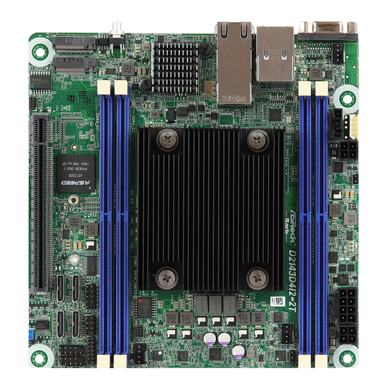
Motherboard Layout
Onboard LED Indicators
I/O Panel
Block Diagram
Chapter 2 Installation
Screw Holes
Pre-Installation Precautions
Installation of Memory Modules (DIMM)
Expansion Slots (PCI Express Slots)
Jumper Setup
Onboard Headers and Connectors
Unit Identification Purpose Led/Switch
Driver Installation Guide
Dual LAN and Teaming Operation Guide
Chapter 3 UEFI Setup Utility
Introduction
UEFI Menu Bar
Navigation Keys
Main Screen
Advanced Screen
CPU Configuration
DRAM Configuration
Chipset Configuration
Storage Configuration
ACPI Configuration
USB Configuration
Super IO Configuration
Serial Port Console Redirection
H/W Monitor
Runtime Error Logging
Instant Flash
Security
Key Management
Boot Screen
Csm(Compatibility Support Module)
Event Logs
Server Mgmt
System Event Log
BMC Network Configuration
Exit Screen
Advertisement
Quick Links
Download this manual
D2143D4I2-2T
D2163D4I2-2T
User Manual
Version 1.0
Published May 2019
Copyright©2019 ASRock Rack INC. All rights reserved.
Table of
Contents
Previous
Page
Next
Page
1
2
3
4
5
Advertisement
Table of Contents
Need help?
Do you have a question about the D21G3D4I2-2T and is the answer not in the manual?
Ask a question
Questions and answers
Related Manuals for ASROCK D21G3D4I2-2T
Motherboard ASRock 890FX Deluxe3 Quick Installation Manual
Quick installation guide (231 pages)
Motherboard ASROCK DN2800MT Easy Setting Manual
Mini-itx atom motherboard (2 pages)
Motherboard ASRock Q2900M User Manual
(60 pages)
Motherboard ASRock D1800M User Manual
Q1900m / d1800m motherboard (64 pages)
Motherboard ASRock Q1900B-ITX User Manual
Motherboard (62 pages)
Motherboard ASROCK Q1900B-ITX User Manual
(52 pages)
Motherboard ASROCK Q1900B-ITX Instruction
(128 pages)
Motherboard ASROCK D1541D4I-2L2T User Manual
Server/workstation (84 pages)
Motherboard ASROCK D1540D4U-2T8R User Manual
(97 pages)
Motherboard ASROCK D1541D4U Series User Manual
Server/workstation motherboard (93 pages)
Motherboard ASROCK D2143D4I2-2T User Manual
Server/workstation motherboard (75 pages)
Motherboard ASROCK D2123D4I4 User Manual
(74 pages)
Motherboard ASROCK DeskMeet B660 Series Manual
(133 pages)
Motherboard ASROCK D1622D4I User Manual
Server/workstation motherboard (74 pages)
Motherboard ASROCK DeskMini B660 User Manual
(67 pages)
Motherboard ASROCK DeskMeet X300 User Manual
(62 pages)
This manual is also suitable for:
D2143d4i2-2t
D2163d4i2-2t
Table of Contents
Print
Rename the bookmark
Delete bookmark?
Delete from my manuals?
Login
Sign In
OR
Sign in with Facebook
Sign in with Google
Upload manual
Upload from disk
Upload from URL


Need help?
Do you have a question about the D21G3D4I2-2T and is the answer not in the manual?
Questions and answers