Advertisement
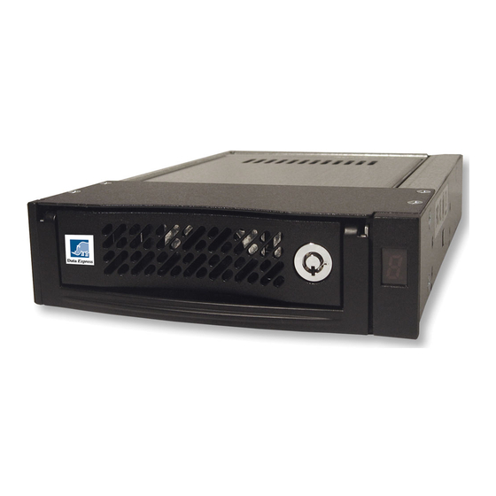
DE110 Ultra320 68-Pin Install Guide
Removable Ultra320 Drive Enclosure
NOTES: DE110 Ultra320 receiving frames are indicated by their AMBER LED, and the
DE110 Ultra320 carriers are indicated by the Ultra320 logo.
For SCSI Ultra320 operation, the DE110 Ultra320 requires Ultra320 drives, Ultra320 HBA,
and Ultra320-compliant cabling (internal and external).
Due to the fixed connector some hard drives will not fit into the DE110 U320 68-pin carrier.
The DE100 U320 68-pin carrier will work with Seagate and Maxtor hard drives.
Receiving Frame Motherboard
I/O Connector (J3) - The input/output connector provides a standard
interface for all Ultra320 signals.
DC Power Connector (P1) - A standard 4-pin DC power connector is
used to accept DC power.
Option Pin Connector (W1)
Remote Unit ID Selection: Pins 1-8 of this connector are provided for
SCSI ID selection through a remote ID selector switch. Remote ID selection
requires that the unit ID switch located on the inside of the receiving frame
be set to "0" (onboard ID selection is set with a switch located on the
inside of the receiving frame as shown in Figure 4).
Factory-Installed Jumpers: There are two (2) jumpers factory-installed
on W1 (Pins 9 & 10 and 21 & 22). DO NOT remove these jumpers!
DC Power
68-Pin I/O
Connector (P1)
Connector (J3)
GND
= Pin 1
{
ID0
ID1
Remote ID Select
ID2
ID3
Figure 1: Receiving Frame Motherboard (Rear View)
Buzzer
Option Pin
Connector (W1)
Factory
Installed
Jumpers (do
not remove
1-800-260-9800
Rugged, Reliable, Mobile, Secure
Installation
1. Carefully insert the drive into the carrier. Slide the drive towards the
Drive Carrier Board, so that the I/O connector on the drive mates
with the connector on the Drive Carrier Board. Turn the drive/carrier
assembly over.
2. Fasten the drive into place with four (4) #6-32 Phillips Flat Head
screws. Some drives may require minor adjustment before securing
into carrier with screws.
3. Install the provided drive cover.
Spacer Plates (optional)
The DE110 Ultra320 is designed to fit most computer systems with
standard 5.25" peripheral slots. The installation of the spacer plates
(provided) may or may not be necessary.
Figure 2: Drive Installation Assembly
www.CRU-DataPort.com
TM
Advertisement
Table of Contents

Related Manuals for CRU Dataport DE110 Series


Summary of Contents for CRU Dataport DE110 Series
- Page 1 Rugged, Reliable, Mobile, Secure DE110 Ultra320 68-Pin Install Guide Removable Ultra320 Drive Enclosure NOTES: DE110 Ultra320 receiving frames are indicated by their AMBER LED, and the DE110 Ultra320 carriers are indicated by the Ultra320 logo. For SCSI Ultra320 operation, the DE110 Ultra320 requires Ultra320 drives, Ultra320 HBA, and Ultra320-compliant cabling (internal and external).
- Page 2 Rugged, Reliable, Mobile, Secure Limited Product Warranty CRU-DataPort (CRU) warrants the Data Express DE110 to be free of sig- nificant defects in material and workmanship for a period of five years from the original date of purchase. CRU’s warranty is nontransferable Activity and is limited to the original purchaser.
Need help?
Do you have a question about the DE110 Series and is the answer not in the manual?
Questions and answers