Table of Contents
Advertisement
Quick Links
DE100 ATA 33 Install Guide
Removable ATA 33 Drive Enclosure
Cable
Cover
(provided)
Disk Drive
(not included)
Power Cable
I/O Cable
ID Select Cable
Receiving
Frame
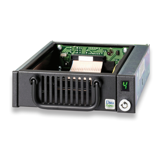
Figure 1: Drive Installation Assembly
Receiving Frame Motherboard
Activity Select Jumper (JP39): Default setting is "A" to use the
activity indicator light on the receiving frame. Set to "B" to use the drive
activity light on the computer chassis.
Master/Slave Selection Jumper (J4A): Master Drive configuration
(default). Forces master drive configuration on receiving frame. Change
jumper to set slave drive configuration, or remove jumper to use unit ID
select switch on receiving frame.
Master/Slave Connection (J6): Used for older model drives that do
not support a Slave Present handshake signal at I/O connector Pin-39.
When using two receiving frames, a connection between J6 may be
required.
Remote Drive Activity (J7): Pins A & C are used for remote drive
activity. All other pins are reserved.
Rugged, Reliable, Mobile, Secure
Drive Carrier
#6-32
Phillips Flat Hd.
Screw
(6 total)
Master/Slave Drive Selection
There are two ways to set the Master/Slave drive designation.
1. Use the factory-installed jumper on your IDE drive - In most
cases, the drive will be factory configured as a Master IDE drive
using a jumper plug on the drive itself. No configuration changes
are required. For multiple drive configurations, it is necessary to set
the first IDE drive as Master and the second IDE drive to Slave. This
can be done by changing the jumper on the IDE drive itself (refer to
the drive manufacturer documentation). This method Requires no
additional configuration of the drive carrier circuit board.
2. Use the hard-wire connector J3 on the drive carrier
circuit board - The Master/Slave drive selection can also be set by
the receiving frame using either Jumper 4A located on the rear panel
or by setting the unit ID select switch. These two methods require the
fabrication of a cable (not provided).
1-800-260-9800
Figure 2: Receiving Frame Motherboard (rear view)
www.CRU-DataPort.com
TM
Advertisement
Table of Contents

Related Manuals for CRU Dataport DE100 ATA 33


Summary of Contents for CRU Dataport DE100 ATA 33
- Page 1 Rugged, Reliable, Mobile, Secure DE100 ATA 33 Install Guide Removable ATA 33 Drive Enclosure Cable Cover (provided) Disk Drive (not included) Power Cable Drive Carrier I/O Cable ID Select Cable Receiving Frame #6-32 Phillips Flat Hd. Screw (6 total) Figure 1: Drive Installation Assembly...
- Page 2 Rugged, Reliable, Mobile, Secure Drive Active Connection NOTES: The unit ID number display is for ID display purposes Slave Connection (J3 Pin 2) only. The master/slave setting must be set on the drive itself. Master Connection (J3 Pin 2) Drive Type Jumpers The lock on the Data Express receiving frame functions as a lock and a DC power switch for the carrier unit.
Need help?
Do you have a question about the DE100 ATA 33 and is the answer not in the manual?
Questions and answers