Table of Contents
Advertisement
Advertisement
Table of Contents

Related Manuals for LTH Electronics MXD75


Summary of Contents for LTH Electronics MXD75
- Page 1 MXD75 Multi-parameter Monitor Installation Guide...
-
Page 3: Preface
Preface Product warranty The MXD75 has a warranty against defects in materials and workmanship for three years from the date of shipment. During this period LTH will, at its own discretion, either repair or replace products that prove to be defective. The associated software is provided ‘as is’... - Page 4 Disposal As per directive 2002/96/EC, please observe the applicable local or national regulations concerning the disposal of waste electrical and electronic equipment. - 2 - MXD75 Installation Guide...
- Page 5 Preface Declaration of Conformity MXD75 Installation Guide - 3 -...
- Page 6 Preface Blank - 4 - MXD75 Installation Guide...
-
Page 7: Table Of Contents
Introduction ......................7 MXD75 Instrument Specification ..............9 Installation – Safety & EMC ................11 Noise suppression ....................12 MXD75 Add-in Cards Installation ..............13 Installation – MXD75 ................... 19 Pipe Mounting ...................... 20 MXD75 Basic Connections ................23 Supply Voltage Connections ..............24 Sensor Connections .................. - Page 8 Contents Blank - 6 - MXD75 Installation Guide...
-
Page 9: Introduction
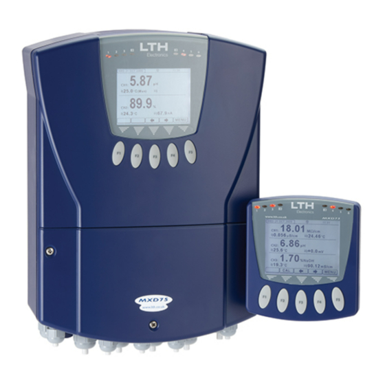
Introduction Introduction The MXD75 is a microprocessor controlled multi-parameter instrument that can be installed with a user selected combination of up to 3 Sensor Input Cards. The instrument may be subsequently modified to meet changing requirements by the installation of additional, or different, cards and the attachment of the appropriate sensor(s). - Page 10 Introduction MXD75 Termination Overview - 8 - MXD75 Installation Guide...
-
Page 11: Mxd75 Instrument Specification
Introduction MXD75 Instrument Specification Input Expansion Slots 3 slots, user configurable with any combination of available input add-in cards. Output Expansion Slots 1 slot, user configurable with an additional output option add-in card. Ambient Operating Temperature -20°C to +50°C (-4°F to +122°F) for full specification. - Page 12 LV Option 18 – 32 V AC or DC, 20W max. Instrument Housing UL 94-V0 PC/ABS. Ingress Protection Rating IP66. (IEC 60529 Protection Rating) Weight Maximum 2.7 kilograms (instrument only). Dimensions 331 x 242 x 110 mm (H, W, D) excluding mounting brackets. - 10 - MXD75 Installation Guide...
-
Page 13: Installation - Safety & Emc
LOCAL WIRING AND SAFETY REGULATIONS SHOULD BE STRICTLY ADHERED TO WHEN INSTALLING THIS UNIT. SHOULD THESE REGULATIONS CONFLICT WITH THE FOLLOWING INSTRUCTIONS, CONTACT LTH ELECTRONICS OR AN AUTHORISED LOCAL DISTRIBUTOR FOR ADVICE. To maintain the specified levels of Electro Magnetic Compatibility (EMC, susceptibility to and emission of electrical noise, transients and radio frequency signals) it is essential that the types of cables recommended within these instructions be used. -
Page 14: Noise Suppression
Fit an in-line mains filter close to the power terminals of the instrument. In cases of very high background RF and HF noise environments, LTH can supply a length of proprietary RF suppressing mains cable. - 12 - MXD75 Installation Guide... -
Page 15: Mxd75 Add-In Cards Installation
The MXD75 can be fitted with up to 3 sensor input cards and 1 output option card. The sensor input cards are designated Input Card 1, Input Card 2 and Input Card 3. On the instrument display these are designated Channel 1, Channel 2 and Channel 3. - Page 16 Insert the required input card or output option card between the headers as shown in the following two diagrams, ensuring that the connectors are correctly aligned with the headers on the cards. Input Card 3 & Output Option Card Installation Side View - 14 - MXD75 Installation Guide...
- Page 17 Input Card 3 & Output Option Card Installation Top View To install the cards and headers into the instrument, first remove the terminal cover. Then remove the two revealed screws at the bottom of the case. MXD75 Installation Guide - 15 -...
- Page 18 Match the header’s name with corresponding text on the board, as shown in the following figure. Care must be taken to align the header board with the dotted outline on the main board. - 16 - MXD75 Installation Guide...
- Page 19 With Input Card 1 and 2 With Input Card 1, 2, 3 and Output Option Card Now attach the supplied connection labels to the terminal area label and inside the terminal cover as shown. Supplied Terminal Label Locations MXD75 Installation Guide - 17 -...
- Page 20 Connect the power (see Supply Voltage Connections section) and check that all of the new cards have been recognised by the instrument. Now consult the appropriate wiring section for details of how to connect the sensors and outputs. - 18 - MXD75 Installation Guide...
-
Page 21: Installation - Mxd75
Installation Installation – MXD75 The MXD75 Surface mount instrument is designed for fixing to a wall or other flat surface. Three 6.5mm diameter holes are provided for this purpose. Note that fasteners are not provided. MXD75 Overall Dimensions LTH Recommends using No. 10 x 1¼... -
Page 22: Pipe Mounting
25 – 70 mm outside diameter. (Optional – LTH Part No. 7599). The instrument is then clamped using the mounting kit as follows. Note: Care should be taken not to over tighten mounting, as damage may result to enclosure. - 20 - MXD75 Installation Guide... - Page 23 Installation Horizontal Mounting Vertical Mounting MXD75 Installation Guide - 21 -...
- Page 24 Installation Blank - 22 - MXD75 Installation Guide...
-
Page 25: Mxd75 Basic Connections
N.B. the appearance of the label will vary depending upon which options are installed in the instrument. MXD75 basic terminal label The cables should be fed through the cable glands. After each cable has been attached, pull most of the cable slack back through the cable gland to prevent any unwanted RF energy from being radiated inside the housing. -
Page 26: Supply Voltage Connections
Supply Voltage Connections The MXD75 can be powered from either an AC or DC supply voltage. The unit provides two terminals for each of the input connections (“Live” & “Neutral” for an AC input, or + & - for a DC Input), plus an “Earth”... -
Page 27: Current Output Connections
Connections Current Output Connections The MXD75 can be supplied with up to 6 current outputs designated A to F, which can terminate into a load resistance not exceeding 750. For best noise immunity use a screened twisted pair cable, with the screen connected to Earth at one end. Use a sufficiently large cable to avoid a high resistance in the overall current loop. -
Page 28: Relay Connections
Connections Relay Connections The MXD75 can be supplied with up to 6 relays designated 1 to 6, 1 to 4 are change over relays while 5 to 6 are normally open relays. The relay contacts are connected to the terminals only and are electrically isolated from the instrument itself. They must be connected in series with a 5 Amp fuse. -
Page 29: Digital Inputs
Connections Digital Inputs The MXD75 features 8 digital inputs, which can be used to initiate a user configurable instrument operation by use of a volt free link, switch or relay. The instrument can be configured to initiate the appropriate action when the contact either closes or opens. -
Page 30: Sd Card Interface
The MXD75 features a SD card interface which is compatible with SD, SDHC and SDXC formatted cards (N.B. SDXC cards may need formatting by the MXD75 before use – see user interface guide). The card can be removed whilst the instrument is on but only when the disk icon is not shown at the top of the display. -
Page 31: Guarantee And Service
LTH manufacture, which are subject to a separate agreement. All sensors made by LTH Electronics Ltd are thoroughly tested to their published specification before despatch. As LTH have no control over the conditions in which their sensors are used, no further guarantee is given, although any complaints concerning their operation will be carefully investigated. - Page 32 Notes - 30 - MXD75 Installation Guide...
- Page 33 Notes MXD75 Installation Guide - 31 -...
-
Page 34: Index
Index Mounting ............19 Connections ..........23 Digital Inputs ........27 Noise Suppression ........12 MXD75 ..........23 Relays ..........23, 26 Output Option Card ........14 Sensors ..........24 Supply Voltage ........24 Pipe-Mounting ..........20 Current Outputs ......... 9 Power Supply ..........10 Digital Inputs .......... - Page 36 Chaul End Lane Luton Bedfordshire LU4 8EZ United Kingdom Telephone: +44 (0) 1582 593693 Fax: +44 (0) 1582 598036 Email: sales@lth.co.uk Web: www.lth.co.uk...
Need help?
Do you have a question about the MXD75 and is the answer not in the manual?
Questions and answers