Table of Contents
Advertisement
Quick Links
Advertisement
Table of Contents

Subscribe to Our Youtube Channel
Related Manuals for LTH Electronics AquaCal 2000


Summary of Contents for LTH Electronics AquaCal 2000
- Page 1 AquaCal 2000 PURE WATER CONDUCTIVITY METER OPERATION GUIDE...
- Page 3 Disclaimer LTH Electronics Ltd reserves the right to make changes to this manual or the instrument without notice, as part of our policy of continued developments and improvements. All care has been taken to ensure accuracy of information contained in this manual. However, we cannot accept responsibility for any errors or damages resulting from errors or inaccuracies of information herein.
- Page 4 Preface Standards Electromagnetic compatibility This instrument has been designed to comply with the standards and regulations called up by the European Directive on EMC Safety This instrument has been designed to comply with the IEC 348-1978 (BS 4743-1979) safety standard to Protection Class 1. Quality This instrument has been manufactured under the following quality standard: ISO 9001:2000.
-
Page 5: Table Of Contents
2 Installation Cells and sampling Connections and cabling D-connector Cell & Pt1000 D-connector - Voltage outputs 3 Operation Viewing the readings Viewing the AquaCal 2000 settings 4 Setting Up Security setting Range and units Units Range Temperature compensation Cell constant... - Page 6 Preface 5 Fault Finding Introduction Faults Instrument appears dead Instrument display appears to malfunction Unable to program the instrument Membrane switch panel appears to malfunction Conductivity reading appears incorrect Temperature reading appears incorrect Voltage outputs appear incorrect or noisy Error messages General System setup and operations Conductivity/resistivity voltage output...
-
Page 7: Introduction
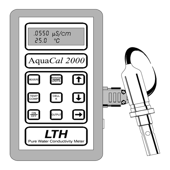
AquaCal 2000 functions The front panel of the AquaCal 2000 provides a direct digital readout of the solution conductivity or resistivity and temperature. The instrument's operations are controlled with nine tactile membrane key switches. - Page 8 1 Introduction The following table summarises the functions provided by each key. In some cases, further functions can be reached by pressing Description ON/OFF Switches the unit ON or OFF MEASURE Displays the conductivity/resistivity and temperature. RANGE/UNITS Displays the range and units and allows changes to be made.
-
Page 9: Analogue Outputs
1 Introduction The following functions are obtained by pressing two keys simultaneously. Keys Followed by Description Displays the error messages flag and allows them to be set IN (messages displayed) or OUT (not displayed). Displays and allows changing of the Auto Power Off time. -
Page 10: Specifications
1 Introduction Specifications Ranges of measurement Conductivity Resistivity Temperature 0 - 0.9999 µS/cm 0 - 999.9 K.cm -10.0 - +110.0°C 0 - 9.999 µS/cm 0 - 9.999 M.cm 0 - 99.99 µS/cm 0 - 99.99 M.cm 0 - 9.999 µS/m 0 - 99.99 µS/m 0 - 999.9 µS/m 0 - 9999 µS/m... - Page 11 1 Introduction Battery type 4 x AA alkaline or NiMH rechargeable Battery life 40 hours continuous with alkaline batteries. NiMH batteries have typically half this life. Low battery warning By a symbol on the display Auto power off Selectable, 1 minute to 40 hours, or disabled. Security Access code entered on the front panel.
- Page 12 1 Introduction This page is intentionally left blank...
-
Page 13: Installation
Refer to Appendix A for extracts from ASTM D5391-99 referring to cell positioning, flow rate and sampling. Although other cells can be used with the AquaCal 2000 instrument, the CMC26/001/PT43 allows measurement to traceable standards. To enable this, the cell is provided with a certified cell constant. The cell constant must be entered on the instrument to ensure accurate readings. - Page 14 2 Installation Note: Hosetail connectors and sealing washers are available as an optional extra. These will fit tubing of 1/4"I.D. Figure 2 Flow chamber...
- Page 15 2 Installation Figure 3 Suspended flow chamber...
- Page 16 2 Installation Figure 4 Connections for battery operation See page 2-5 for wiring information. ...
-
Page 17: D-Connector Cell & Pt1000
2 Installation D‐connector Cell & Pt1000 C (centre electrode) 6 G (guard) E (outer electrode) 7 Earth/shield Earth/shield 8 T4 9 T3 T1 and T3 are connected to one side of the Pt1000. T2 and T4 are connected to the other side of the Pt1000. Note: the 4 wire connection to the RTD must be maintained for instrument accuracy. - Page 18 2 Installation This page is intentionally left blank...
-
Page 19: Operation
3 Operation Operation This chapter explains the AquaCal 2000 display and the operational functions available from the front panel membrane switches. The AquaCal 2000 functions are selected using six operation keys in conjunction with the three modifier keys - The main functions are selected by pressing the corresponding key on its own. -
Page 20: Viewing The Aquacal 2000 Settings
3 Operation Viewing the AquaCal 2000 settings The following table shows the functions for viewing each of the AquaCal 2000 settings. In many cases, the operational key displays a sequence of settings which you step through by pressing To view... - Page 21 3 Operation To view Press Display shows (example) Output : TEMP Zero Span 100.0 C Error Messages Errors In (error messages displayed) or setting Errors Out (not displayed). Auto off setting Auto off 0:10 Hh:Mm Filter setting Filter In (measurements averaged) or Filter Out (not averaged) Security setting 0000...
- Page 22 3 Operation This page is intentionally left blank...
-
Page 23: Setting Up
Setting Up This chapter describes the recommended procedure for setting up and configuring the AquaCal 2000. When pressing a key, hold it down for about half a second or just long enough to produce the desired effect. Holding a key down for more than one second causes repeated action of the key function, where appropriate. -
Page 24: Range And Units
4 Setting up Press Display shows Explanation (example) Security Out Display change to allow user to change setting Security Out The setting flashes Security In Change the setting Security In Enter the setting Press MEASURE to leave the security screen. Range and units The ranges that are available (see page 1-4) depend on the units selected. - Page 25 4 Setting up Press Display shows Explanation (example) Range Units The units flash Auto µS/cm Range Units Change the units as required Auto M.cm Range Units Enter the new units Auto M.cm If a range change is now required, follow the procedure for changing the range, omitting the first step.
-
Page 26: Range
4 Setting up Range Display shows Press Explanation (example) Range Units The present range and units are Auto µS/cm displayed (If necessary) Range Units The range flashes Auto µS/cm Range Units Set the range as required 9.999 µS/cm Range Units The units flash 9.999 µS/cm... -
Page 27: Temperature Compensation
4 Setting up Temperature compensation Display shows Press Explanation (example) Base Slope The present settings are 25°C 2.0%/°C displayed. Note: If TC is Out, Base and Slope are not displayed as they are not relevant. Base Slope The T.C. In (or Out) flashes 25°C 2.0%/°C Press... -
Page 28: Cell Constant
4 Setting up Press Display shows Explanation Base Slope Set the digit 20°C 1.9%/°C Base Slope Enter the slope value 20°C 1.9%/°C Cell constant Press Display shows Explanation Cell Constant The present setting is 0.01000 displayed Cell Constant The digit '1' flashes. This digit can only be set as either 1 or 0, 0.01000 as the cell constant can only be... -
Page 29: Output
4 Setting up Output Display shows Press Explanation (example) Output : COND Output : COND COND flashes Output : TEMP Toggles between TEMP and COND The next screen depends on whether COND or TEMP is selected, see page 4-9 for COND settings. Temperature output ... - Page 30 4 Setting up Press Display shows Explanation (example) Increment or decrement the flashing digit Enter the flashing digit and move to the next digit Repeat steps 8 and 9 for each digit of both zero and span values. When the last digit is flashing, press to confirm the settings.
-
Page 31: Conductivity Output
4 Setting up Conductivity output Press Display shows Explanation (example) Output : COND COND flashes Output : COND Output Range The present output range is 9.999 µS/cm displayed Output Range 9.999 µS/cm Note: The conductivity output units must be the same as the measurement units. -
Page 32: Error Messages, Auto Power Off And Input Filter
4 Setting up Error messages, auto power off and input filter Note: Some of the following steps should be omitted where changes are not required to all of the settings. Press Display shows Explanation (example) Errors In Error messages will be displayed. Errors In In flashing. - Page 33 4 Setting up Press Display shows Explanation (example) Repeat steps 8 and 9 for each digit. The data is entered into memory during step 9 for the last digit. To confirm Auto Off time. Instead of displaying each measurement as it is made, the Filter option displays the average of the last 16 measurements, thus reducing any fluctuations due to variations of the water conductivity at the sample point.
- Page 34 4 Setting up This page is intentionally left blank 4-12...
-
Page 35: Fault Finding
5 Fault finding Fault Finding Introduction Note: THERE ARE NO USER SERVICEABLE PARTS INSIDE THE UNIT. A set of error messages has been built into the system to aid fault finding and diagnosis. If one of these messages is being displayed, refer to the table at the end of this section;... -
Page 36: Faults
5 Fault finding Faults Instrument appears dead Check that batteries are fitted and have correct polarity. Remove batteries for a few seconds, then replace them and switch on. This checks that a programme latch-up has not occurred. Instrument display appears to malfunction Switch off (or remove batteries) and on again. Check that the display shows full blocks for five seconds, followed by the Software Issue number. -
Page 37: Temperature Reading Appears Incorrect
5 Fault finding If another sensor is available, this can be used to determine whether the fault lies with the instrument or the sensor. Check that the temperature compensation base temperature is set correctly to 20°C or 25°C, as required. Check that the sensor cable is not damaged or broken and that the screen does not make contact with any other terminals or metal work. -
Page 38: Voltage Outputs Appear Incorrect Or Noisy
5 Fault finding Voltage outputs appear incorrect or noisy Check that the load resistance is not less than 10K. Check that the plug and cable is not broken or damaged (see 9 way D- connector details in Section 2). If a junction box is used, check that it has been wired correctly. Check that the cable is not too close to power cables, contactors, motors etc. -
Page 39: General
5 Fault finding General Error Description Action/Explanation Main input saturation. Solution conductivity/resistivity is too Er01 high, for the selected range, or is at an extreme of temperature. See the appendices for details. Main input saturation. Solution conductivity/resistivity is too Er02 low, for the selected range, or is at an extreme of temperature. -
Page 40: System Setup And Operations
5 Fault finding System setup and operations Error Description Action/Explanation Instrument range corrupted. Check units and operating range. Er11 Instrument units corrupted. Check units and operating range. Er12 Conductivity/resistivity voltage output operations This is only available when the Output option is fitted. Error Description Action/Explanation Measurement units do not Set output range, zero and span. -
Page 41: Temperature Voltage Output Settings
5 Fault finding Temperature voltage output settings This is only applicable when the output option is fitted. Error Description Action/Explanation Voltage output zero setting Er31 is greater than span setting. Check zero and span settings. Voltage output span is less Er32 ... -
Page 42: Floating-Point Mathematical Routines
5 Fault finding Floating‐point mathematical routines Error Description Action/Explanation Overflow error. Internal maths computation fault. Er51 Check operating conditions first. Underflow error. Internal maths computation fault. Er52 Check operating conditions first. Divide by 0 error. Internal maths computation fault. Er53 Check operating conditions first. Too large for conversion Internal maths computation fault. -
Page 43: Guarantee And Service
6 Guarantee and service Guarantee and service Products manufactured by LTH Electronics Ltd are guaranteed against faulty workmanship and materials for a period of three years from the date of despatch, except for finished goods not of LTH manufacture, which are subject to a separate agreement. - Page 44 6 Guarantee and service This page is intentionally left blank...
-
Page 45: Appendix A Cell Positioning, Flow Rate And Sampling
App A Cell positioning Appendix A Cell positioning, flow rate and sampling This is a summary of ASTM D5391-99, combined with LTH application notes. Pure water conductivity or resistivity must be measured with a cell and temperature sensor in a flowing, closed system to prevent trace contamination from wetted surfaces and from the atmosphere. - Page 46 App A Cell positioning Conductivity cells mounted downstream from ion exchangers are vulnerable to catching ion exchange resin particles between the cell electrodes. Resin particles are sufficiently conductive to short circuit the cell and cause high off scale conductivity or extremely low resistivity readings. Resin retainers must be effective and the cell must be installed so that it is accessible for cleaning.
-
Page 47: Temperature Coefficient Of A
If the temperature coefficient of the solution being monitored is not known, the AquaCal 2000 can be used to determine that coefficient. You should set the AquaCal 2000 to auto ranging, with the temperature compensation IN and the temperature coefficient to 0.0%. - Page 48 App B Calculating temp. coefficient This page is intentionally left blank...
-
Page 49: Index
Index Index Accuracy Ambient temperature Error messages 5-1, 5-4 Aquacal Settings, viewing Error messages flag Atmospheric effects Error messages setting 3-3, 4-10 Auto off setting Auto power off 1-5, 4-10 Auto power off time Fault finding Filter setting Flow chamber Battery 1-5, 5-2 Flow rate... - Page 50 Index pH Sensors Power supply Programming Range 3-2, 4-2, 4-4, 5-3, 5-6 Range units Ranges Repeatability Resin particles Resistivity Resistivity output Sampling 2-1, A-1 Saturation of input Security code 3-3, 4-1 Service Setting up Specification Temperature Temperature compensation 1-4, 3-2, 4-5, A-1 Temperature output Trace contamination Traceable calibration...
-
Page 51: Quick Reference
Press ON/OFF to turn the AquaCal 2000 on (and off). Press MEASURE to display conductivity and temperature. Setting security To prevent tampering with parameters, the AquaCal 2000 can be locked. To lock or unlock the settings, press together. Enter the code '1582' and set security to IN to enable or OUT to prohibit setting. - Page 52 selected, no further setting is required. If IN is selected, the base temperature has to be set (20°C or 25°C). The next setting is slope, which is adjustable between 0.0%/°C and 3.9%/°C. Cell constant Press CELL K. The cell constant can be set between 0.00900 and 0.01100 0.01000 ±...
- Page 56 LTH Electronics Ltd Chaul End Lane Luton Bedfordshire LU4 8EZ United Kingdom Telephone : +44 (0) 1582 593693 Fax : +44 (0) 1582 598036 e-mail : sales@lth.co.uk web : www.lth.co.uk...
Need help?
Do you have a question about the AquaCal 2000 and is the answer not in the manual?
Questions and answers