Table of Contents
Advertisement
Quick Links
Advertisement
Table of Contents

Related Manuals for LTH Electronics BMD17


Summary of Contents for LTH Electronics BMD17
- Page 1 BMD17 mA Input Monitor Operation Guide...
-
Page 2: Preface
Disclaimer LTH Electronics Ltd reserves the right to make changes to this manual or the instrument without notice, as part of our policy of continued developments and improvements. All care has been taken to ensure accuracy of information contained in this manual. - Page 3 Disposal As per regulation S.I. 2012/3032 and directive 2012/19/EU, please observe the applicable local or national regulations concerning the disposal of waste electrical and electronic equipment. BMD17 mA Input Monitor - 2 - Operating Guide...
- Page 4 Preface Declaration of Conformity BMD17 mA Input Monitor - 3 - Operating Guide...
- Page 5 Preface BMD17 mA Input Monitor - 4 - Operating Guide...
-
Page 6: Table Of Contents
Digital Inputs ....................19 MicroSD Card Interface ................19 Installation ......................20 BMD17 mA Input Connection Details ............ 21 User Interface......................24 The Front Screen .................... 24 Security Code Access ..................26 ... - Page 7 Save, Restore & Reset ..................58 Service ........................60 Service Alarm ....................60 Appendix A - Error Messages................. 61 Fault Finding ......................64 Guarantee and Service ..................65 BMD17 mA Input Monitor - 6 - Operating Guide...
-
Page 8: Introduction
Introduction Introduction The BMD17 is a microprocessor-controlled mA Input measurement instrument that can be used with a variety of loop powered and self-powered current output transmitters. To achieve this, the instrument utilises a multifunction LCD to display the primary reading and raw mA Input, show operational status and to provide an intuitive user interface. -
Page 9: Ma Input Specification
Input – Standard mA input from transmitter, 100Ω input Loop Modes impedance, max loop voltage 35V. Loop Powered – The BMD17 will supply 24V to power the current loop. 3 Wire – The BMD17 can supply an alternative 24V 30mA Max output via the “24v PWR”... - Page 10 LV Option 12 – 30 V DC, 6W max. UL 94-V0 PC/ABS. Instrument Housing IP66. Ingress Protection Rating (IEC 60529 Protection Rating) Maximum 800 grams (instrument only). Weight 175 x 150 x 119 mm (H, W, D). Dimensions BMD17 mA Input Monitor - 9 - Operating Guide...
- Page 11 Specification Blank BMD17 mA Input Monitor - 10 - Operating Guide...
-
Page 12: Installation - Safety & Emc
LOCAL WIRING AND SAFETY REGULATIONS SHOULD BE STRICTLY ADHERED TO WHEN INSTALLING THIS UNIT. SHOULD THESE REGULATIONS CONFLICT WITH THE FOLLOWING INSTRUCTIONS, CONTACT LTH ELECTRONICS OR AN AUTHORISED LOCAL DISTRIBUTOR FOR ADVICE. To maintain the specified levels of Electro Magnetic Compatibility (EMC, susceptibility to and emission of electrical noise, transients and radio frequency signals) it is essential that the types of cables recommended within these instructions be used. -
Page 13: Noise Suppression
Use the internal relays to switch external slave relays or contactors when switching heavy or reactive loads. Fit an in-line mains filter close to the power terminals of the instrument. BMD17 mA Input Monitor - 12 - Operating Guide... -
Page 14: Enclosure
Installation Enclosure The BMD17 as standard is designed to be mounted on a wall or surface via the two holes located in the rear half of the enclosure. Alternatively, it can be mounted to a panel or a pipe using optional mounting kits. -
Page 15: Surface-Mounting
Care must be taken when fitting the instrument on uneven walls or surfaces. Once installed make sure accompanying IP protection plugs are installed over the mounting holes on the inside rear of the enclosure. BMD17 mA Input Monitor - 14 - Operating Guide... -
Page 16: Panel-Mounting
Attach the Mounting Plate to the rear of the case with the supplied screws. To pass instrument rear through panel cut out remove cable glands. Use the 4 supplied screw clamps to affix the instrument to the panel. BMD17 mA Input Monitor - 15 - Operating Guide... -
Page 17: Pipe-Mounting
Pass supplied mounting straps through plate loops and tighten round pipe as required. Fit the accompanying IP protection plugs over the internal mounting holes on the inside rear of the enclosure. BMD17 mA Input Monitor - 16 - Operating Guide... -
Page 18: Terminal Operation
Supply Voltage Connections Depending upon version purchased BMD17 can be powered from either 90-265V AC or 12- 30V DC supply voltage. Refer to the label adjacent to the power supply terminals for the input voltage limits. Exceeding these limits may damage the instrument. -
Page 19: Relay Connections
Installation Relay Connections The BMD17 is supplied with 2 normally open volt free relays designated 1 & 2, The relay contacts are connected to the terminals only and are electrically isolated from the instrument itself. They must be connected in series with a 5 Amp fuse. A contact arc suppressor may be required to prevent excessive electrical noise, depending upon the load. -
Page 20: Digital Inputs
Installation Digital Inputs The BMD17 features a single digital input, which can be used to initiate a user configurable instrument operation by use of a volt free link, switch or relay. The instrument can be configured to initiate the appropriate action when the contact either closes or opens. -
Page 21: Installation
Installation Installation The BMD17 mA Input Monitor allows the user to read the current output of a variety of loop powered and self-powered transmitters. Self-Powered Transmitters For self-powered transmitters the current input of the BMD17 is isolated from the instrument‘s power supply thus allowing the input to be connected in series with other devices on the loop if the loop is fed from a single ended transmitter. -
Page 22: Bmd17 Ma Input Connection Details
Installation BMD17 mA Input Connection Details mA Input Connection Details Internally Powered Loop Connection Details (BMD17 powers the loop with 24V) BMD17 mA Input Monitor - 21 - Operating Guide... - Page 23 Installation Locally Powered Transmitter Loop Connection Details Externally Powered Loop Connection Details BMD17 mA Input Monitor - 22 - Operating Guide...
- Page 24 Installation 3 Wire Transmitter Loop Connection Details (NB. The 24V Can Supply 30mA Max) BMD17 mA Input Monitor - 23 - Operating Guide...
-
Page 25: User Interface
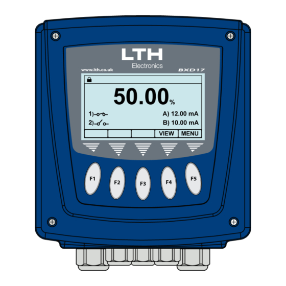
FOLLOWED CORRECTLY. FAILURE TO DO SO MAY RESULT IN AN ELECTRICALLY HAZARDOUS INSTALLATION OR IRREPARABLE DAMAGE TO THE INSTRUMENT. The BMD17 uses a 3¾” 240x128 dot LCD Module to display the primary reading, show operational status and to provide an intuitive user interface. This is accompanied by 5 control buttons whose function varies depending upon which screen the user is viewing. - Page 26 The exit button is used to return to the previous menu. If no buttons are pressed after 2 minutes the instrument will default back to the front screen. BMD17 mA Input Monitor - 25 -...
-
Page 27: Security Code Access
If the code is correct the padlock at the top of the screen will turn to a key and the unit will be unlocked / – Increase / Decrease Digit – Select Next Digit EXIT – Cancel – Enter Code BMD17 mA Input Monitor - 26 - Operating Guide... -
Page 28: Ma Input Setup
If a curve is chosen and the input falls below the lowest or highest entered mA input point, an error is generated. / – Select Option – Cancel EXIT – Save Selection BMD17 mA Input Monitor - 27 - Operating Guide... -
Page 29: Units
Enter the displayed value equivalent to a 0mA input. Note. Only available when input mode is set to 0mA – 20mA input. / – Increase / Decrease Digit – Select Next Digit – Cancel EXIT – Save Value BMD17 mA Input Monitor - 28 - Operating Guide... -
Page 30: Setup Curve A Or B
5 characters. Curve Range – Select the operating range over which the curve is scaled. Data Points – Enter the mA input and equivalent curve value. BMD17 mA Input Monitor - 29 - Operating Guide... -
Page 31: Input Filtering (Averaging)
Note, only enabled setpoints or current outputs will be shown. / – Increase / Decrease Digit – Select Next Digit – Cancel EXIT – Use Entered Value BMD17 mA Input Monitor - 30 - Operating Guide... -
Page 32: Calibration
From the main menu highlight “calibration” and press the enter option button to show the channel menu options. / – Select Option – Return to Main Menu EXIT – Enter Option BMD17 mA Input Monitor - 31 - Operating Guide... - Page 33 Only available when the input mode is set to 0 – 20mA in the channel menu. – Go to Previous Calibration Point PREV SKIP – Skip to Next Calibration Point – Exit Calibration Without Saving EXIT – Initiate Calibration BMD17 mA Input Monitor - 32 - Operating Guide...
- Page 34 The calculated offset is shown in the next menu entry. / – Adjust the Reading Up or Down – Cancel EXIT – Save Calibration BMD17 mA Input Monitor - 33 - Operating Guide...
-
Page 35: Front Screen Calibration Access
The Next Cal Date will update to show the date of the next calibration alarm. / – Increase / Decrease Digit – Select Next Digit – Cancel EXIT – Save Value BMD17 mA Input Monitor - 34 - Operating Guide... - Page 36 – Select Option EXIT – Return to Main Menu – Enter Option Reset Solution Reset the solution calibration. / – Select Option – Return to Main Menu EXIT – Enter Option BMD17 mA Input Monitor - 35 - Operating Guide...
-
Page 37: Setpoints
Setpoints Setpoints The BMD17 is be fitted with two “Normally Open” setpoint relays designated Setpoint 1 and Setpoint 2. The Setpoint menu contains all the necessary setup functions to configure the setpoint. The instrument indicates the status of the relay by means of a symbol on the front screen. - Page 38 It will then remain inactive until the reading level falls below the setpoint low level. BMD17 mA Input Monitor - 37 - Operating Guide...
- Page 39 - which is akin to a normally closed relay except it will fall open if the power to the instrument is removed. / – Select Option – Cancel EXIT – Save Selection BMD17 mA Input Monitor - 38 - Operating Guide...
- Page 40 Time Proportional -- - See Setpoint proportional Mode Section. Menu only available when trigger is set to either high or low / – Select Option – Cancel EXIT – Save Selection BMD17 mA Input Monitor - 39 - Operating Guide...
- Page 41 Note. Only available when Trigger is set to High, Low or Band and Mode is set to On-Off. / – Increase / Decrease Digit – Select Next Digit EXIT – Cancel – Save Value BMD17 mA Input Monitor - 40 - Operating Guide...
-
Page 42: Hysteresis
– Save Value Unit Flash on Trigger When enabled the backlight of the unit will flash when the setpoint has been triggered. / – Select Option EXIT – Cancel – Save Selection BMD17 mA Input Monitor - 41 - Operating Guide... -
Page 43: Setpoint Dose Alarm
– Clear Setpoint 1 Dose Alarm ACK 1 – Clear Setpoint 2 Dose Alarm ACK 2 – Access Main Menu MENU BMD17 mA Input Monitor - 42 - Operating Guide... - Page 44 – Save Selection Start Initial Charge The user can also start the initial charge via this option in the setpoint menu. / – Select Option EXIT – Cancel – Save Selection BMD17 mA Input Monitor - 43 - Operating Guide...
-
Page 45: Setpoint Cleaning Mode
– Cancel EXIT – Save Value Clean Interval Enter the time between cleaning operations. / – Increase / Decrease Digit – Select Next Digit – Cancel EXIT – Save Value BMD17 mA Input Monitor - 44 - Operating Guide... - Page 46 / – Select Option EXIT – Cancel – Save Selection Manual Clean This manually starts a clean cycle. / – Select Option – Cancel EXIT – Save Selection BMD17 mA Input Monitor - 45 - Operating Guide...
-
Page 47: Setpoint Proportional Mode
100% of the cycle time. The cycle time is adjustable and is the sum of the on and off times. (See Setpoint Cycle Time – Time Proportional Mode section on the diagram below.) BMD17 mA Input Monitor - 46 - Operating Guide... - Page 48 Enter the size of the Proportion Band. Only available when Mode is set to Pulse or Time Proportion. / – Increase / Decrease Digit – Select Next Digit EXIT – Cancel – Save Value BMD17 mA Input Monitor - 47 - Operating Guide...
-
Page 49: 0/4-20Ma Output
0/4-20mA Output 0/4-20mA Output The BMD17 is fitted with two current outputs, either which can be used for the transmission of the primary variable. The current output menu contains all the necessary setup functions to configure the current output sources. The instrument will display the status of the current output on the front screen, where --.--mA indicates that the output is disabled. -
Page 50: On Error
(i.e. Sensor Fault), to provide remote warning of error conditions or to ensure fail safe operation. / – Select Option EXIT – Cancel – Save Selection BMD17 mA Input Monitor - 49 - Operating Guide... -
Page 51: Calibration
Using the and buttons adjust the current output until it reads the desired value on your current meter. Only used when the mode is set to 4-20mA / – Adjust Output – Cancel EXIT – Save Adjustment BMD17 mA Input Monitor - 50 - Operating Guide... - Page 52 – Cancel EXIT – Save Adjustment Reset Calibration Used to reset any user calibration applied to the 0/4- 20mA Output / – Select Option EXIT – Return to Calibration – Enter Option BMD17 mA Input Monitor - 51 - Operating Guide...
-
Page 53: Digital Inputs
Digital Inputs Digital Inputs The BMD17 is fitted with a single digital input. The digital input menu contains all of the necessary setup functions to configure the digital input sources. This input is intended to be switched using a volt free link, switch or relay. The user can select whether closing or opening the contact initiates the configured action. -
Page 54: Polarity
– Save Selection Polarity Configure whether the digital input activates on the closing of circuit (normal) or the opening of the circuit (reverse). / – Select Option – Cancel EXIT – Save Selection BMD17 mA Input Monitor - 53 - Operating Guide... -
Page 55: Configuration
– Save Selection Set Time/Date Sets the instruments time and date. / – Increase / Decrease Digit / Item – Select Next Digit / Item EXIT – Cancel – Save Time BMD17 mA Input Monitor - 54 - Operating Guide... -
Page 56: Unit Flash On Error
– Return to Configuration Menu EXIT – Enter Option Software Version Displays the instrument’s current software version number (Non-selectable). / – Select Option EXIT – Return to Main Menu – Enter Option BMD17 mA Input Monitor - 55 - Operating Guide... -
Page 57: Serial Number
– Select Option – Return to Main Menu EXIT – Enter Option Contact Information Display the contact information. / – Select Option – Return to Main Menu EXIT – Enter Option BMD17 mA Input Monitor - 56 - Operating Guide... -
Page 58: Update Software
Configuration Update Software The BMD17 operating software can be upgraded by saving the latest version from LTH onto a micro SD card, inserting it into the instrument and following the instructions below. All three files must be present on the SD card for the update to work. The instrument supports SDHC and SDXC cards;... -
Page 59: Save, Restore & Reset
Save, Restore & Reset Save, Restore & Reset The BMD17 features the ability to save and restore the current configuration of the channel, setpoints, current outputs, and digital inputs to one of two stores “A and B”. The save and restore menu also features the ability to reset the whole instrument back to its factory settings. - Page 60 Save, Restore & Reset Restore Setup Restore either of the previously saved setups. Delete Setup Delete the either of the previously saved setups. Default Instrument Reset the whole instrument back to its factory settings. BMD17 mA Input Monitor - 59 - Operating Guide...
-
Page 61: Service
Service Service The BMD17 features a service reminder system that will inform the user when the instrument is due its service. Service Alarm Service alarm configuration: Service Reminder – Turn the service alarm on or off. Requires service security code prior to use. -
Page 62: Appendix A - Error Messages
Reading Under Range The converted sensor reading is less than the specified converted lower limit, check channel settings, sensor condition and connections. If the message persists, please consult with your supplier. BMD17 mA Input Monitor - 61 - Operating Guide... - Page 63 Tel. 0044 (0) 1582 593693 Fax 0044 (0) 1582 598036 Email sales@lth.co.uk NB. LTH overseas users should contact their LTH distributor – See www.lth.co.uk for details. Calibration Due The user entered calibration interval has expired. BMD17 mA Input Monitor - 62 - Operating Guide...
- Page 64 Faults Service Mode Active The unit is currently in service mode, the setpoints and current outputs may not respond as configured. Please contact LTH Electronics at the details below: LTH Electronics ltd Chaul End Lane Luton Beds LU4 8EZ Tel. 0044 (0) 1582 593693 Fax 0044 (0) 1582 598036 Email sales@lth.co.uk...
-
Page 65: Fault Finding
Check that power is available to the unit. Using a voltmeter, set to AC or DC, check the power supply voltage at the connector. The design of the BMD17 allows the unit to accept from 90 to 265V AC, an alternative option allows operation from 12 to 30V DC, check the connection label for voltage specification. -
Page 66: Guarantee And Service
All sensors made by LTH Electronics Ltd are thoroughly tested to their published specification before despatch. As LTH have no control over the conditions in which their sensors are used, no further guarantee is given, although any complaints concerning their operation will be carefully investigated. - Page 67 Faults Blank BMD17 mA Input Monitor - 66 - Operating Guide...
- Page 69 Chaul End Lane Luton Bedfordshire LU4 8EZ United Kingdom Telephone: +44 (0) 1582 593693 Fax: +44 (0) 1582 598036 Email: sales@lth.co.uk Web: www.lth.co.uk...
Need help?
Do you have a question about the BMD17 and is the answer not in the manual?
Questions and answers