Table of Contents
Advertisement
Quick Links
Installation/Wiring Instructions
Smoke and Fire Detector Models DI-3, DI-3H, DI-3IS*, DI-A3, and DI-A3H
To initiating circuit of
compatible control
unit (See †NOTE and
Compatibility Chart)
Connection for listed remote lamp
RL-30 or equivalent, audible base
ADB-3, or relay RR-3, 40mA max, at
24V (one per detector.) CAUTION: Only
one critical function remote should be
used in each circuit, since only one alarm
per circuit is guaranteed.
*
NOTE: The DI-3IS is FM listed only. Do not use remote function with the DI-3IS.
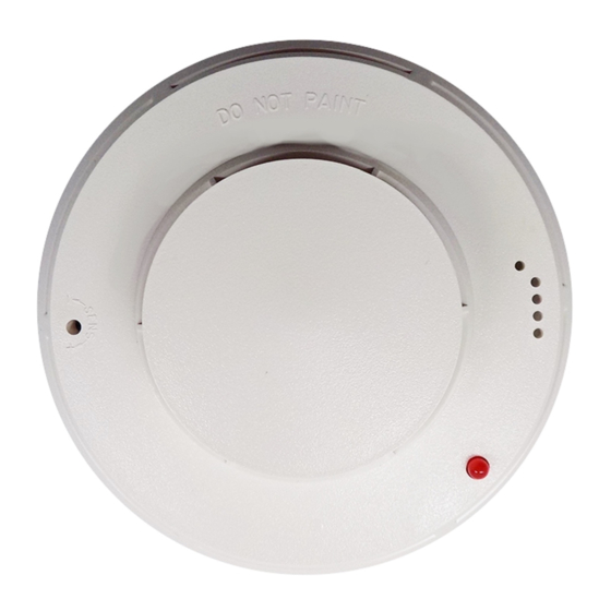
Figure 1
SIEMENS Models DI-3, DI-3H, DI-3IS, DI-A3, AND DI-A3H
Installation And Wiring Diagram
These instructions are written in accordance with the
installation guidelines of NFPA 72, National Fire Alarm
Code, and CAN/ULC-S524, The Installation of Fire Alarm
Systems.
DETECTOR PLACEMENT
Although no specific spacings have been allocated for the
detectors used for the 0 to 300 ft/min clean air velocity
application, use 30 foot center spacing (900 sq ft) from NFPA
Standard 72 Chapter 5 and CAN/ULC-S524, if practical, as a
guide or starting point for a detector installation layout. This
spacing, however, is based on ideal conditions — smooth
ceiling, no air movement, and no physical obstructions. In
some applications, therefore, considerably less area is
protected adequately by each smoke detector. This is why it
is mandatory to closely follow the installation drawings. In all
installations (except in special circumstances, such as in
computer room underfloors where the velocity may be
between 300 and 1200 ft/min) the detector should be located
on the ceiling, a minimum of 6 inches from a side wall, or on
a wall, 6 inches from the ceiling.
Should questions arise regarding detector placement,
drawings provided or approved by Siemens Industry, Inc., or
by its authorized distributors should be followed. This is
extremely important! The detector placements shown on
these drawings have been chosen after a careful evaluation
P/N 315-081943-19
†NOTE: The Models DI-3, DI-3H, DI-3IS*, DI-A3, and
DI-A3H are rated at 16-25.7 VDC—3 volt peak to
peak maximum ripple. Supervisory current 110μA
max steady state. 350μA peak surge upon
application of power, and 135mA max in alarm.
of all facets of the area being protected. Such factors as air
currents, temperature, humidity, pressure, and the nature of
the load have been carefully considered. Especially noted have
been the room or area configuration and the type of ceiling
(sloped or flat, smooth or beamed). Siemens Industry, Inc.'s
extensive experience in the design of the system assures the
optimum detector placement and is reflected in these drawings.
Sound engineering judgment by qualified personnel must
prevail.
TO AVOID NUISANCE ALARMS:
DO NOT locate the DI-3, DI-3H, or DI-3IS detectors where
excessive smoke concentrations exist under normal conditions
or in areas of prolonged high relative humidity where
condensation will occur.
DO NOT locate the DI-3, DI-3H, or DI-3IS detectors adjacent
to an oil burner, kitchen, or garage where exhaust fumes could
trigger an alarm. Other causes of false alarms are dust
accumulation, high wind velocity, heavy concentrations of
steam, heavy pipe or cigar smoke, and certain aerosol sprays.
DO NOT locate the DI-A3 or DI-A3H detectors in an area of
prolonged high relative humidity when condensation will occur
or adjacent to oil burners or in garages, where exhaust fumes
could trigger an alarm.
Building Technologies Division
End-of-line
device
observe
polarity
if applicable
P/N 315-081882, Rev. 2
Siemens Industry, Inc.
Advertisement
Table of Contents

Related Manuals for Siemens DI-3


Summary of Contents for Siemens DI-3
- Page 1 Installation/Wiring Instructions Smoke and Fire Detector Models DI-3, DI-3H, DI-3IS*, DI-A3, and DI-A3H To initiating circuit of compatible control End-of-line unit (See †NOTE and device Compatibility Chart) observe polarity if applicable †NOTE: The Models DI-3, DI-3H, DI-3IS*, DI-A3, and Connection for listed remote lamp RL-30 or equivalent, audible base DI-A3H are rated at 16-25.7 VDC—3 volt peak to...
- Page 2 The depth of the box is determined TEMPERATURE AND HUMIDITY by the National Electrical Code for the number and size of The temperature range for Models DI-3, DI-3H, DI-3IS, DI- the conductors used. A3, and DI-A3H is 32...
- Page 3 Access to the sensitivity adjustment potentiometer is through CAUTION: UNDER NO CIRCUMSTANCES IS THE a hole located on the detector head face. The DI-3, DI-3H, DETECTOR HEAD TO BE DISASSEMBLED. NO FIELD and DI-3IS sensitivity is adjustable ± 0.50 VDC of the nominal REPAIRS SHOULD BE ATTEMPTED.
- Page 4 Siemens Industry, Inc. Siemens Building Technologies, Ltd. P/N 315-081943-19 Building Technologies Division Fire Safety & Security Products Florham Park, NJ 2 Kenview Boulevard Brampton, Ontario L6T 5E46 Canada...
Need help?
Do you have a question about the DI-3 and is the answer not in the manual?
Questions and answers