Advertisement
Quick Links
1
STEP
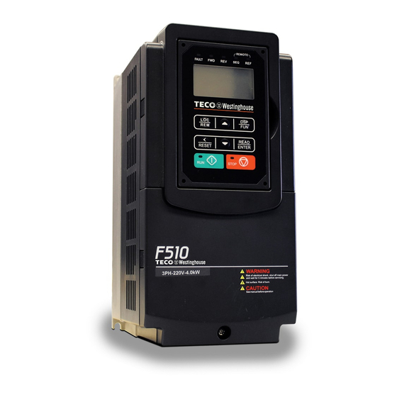
Check Nameplate and Connect Input / Output Wiring -
Check the inverter nameplate to insure that the information agrees with your order. Also insure that the power available is rated
appropriately for the drive being used.
Note: For 1Ø Input use terminals L1 - L3
2
STEP
Power-up the Inverter, check the Digital Operator
In this step, after the initial power-up you will become familiar with the indications and functions of the Digital Operator.
Forward
Reverse Direction
Direction
Status Indicator
Status Indicator
Fault Status
Indicator
Monitor
Fref Ref
12-16=005.00Hz
12-17=000.00Hz
12-18=0000.0A
Run Status
Indicator
KEYS (8) Description
RUN: RUN Inverter in Local Mode
STOP: STOP Inverter
LOC/REM: Switches between Local and Remote operation
DSP/FUN: Switches between available displays
</RESET:
Left Shift: Used to change parameters or values, RESET
alarms and faults
ENTER: Used to display the preset value of parameters and to save
changes
Parameters navigation Up, Increase parameters or reference value
Parameters navigation Down, Decrease parameters or reference value
OUT of the Box Startup – Overview
This document is intended as a quick start guide to get familiarity with keypad
navigation, changing parameters, and setting the F510 drive up for external
start/stop and external potentiometer signal. Please note this document is not
a substitute for the F510 User Manual and it is important that you reference the
F510 user manual before proceeding.
L1
L2
L3
INPUT POWER
Appropriate Input
Ground
Power
3Ø Input
NOTE: Properly check the
GROUND CONNECTION
External Sequence
Indicator
External Reference
Indicator
LCD Display
8 button
Membrane Keypad
Stop Status Indicator
Remove protective covers to access
Secure the Inverter in
the power terminal blocks. (Refer to
a suitable location
the F510 User Manual for detailed
instructions.)
T1
T2
T3
MOTOR
To reverse direction
of motor rotation
swap any two leads
3Ø Induction Motor
F510 Control Settings (Factory Default)
RUN/STOP Control:
Keypad (RUN / STOP key)
Press RUN to start the drive or STOP to stop the drive.
See step 5. to change to RUN/STOP to external switch/contact.
SPEED Control:
Keypad (Default 5.00 Hz)
See step 6. to change to external potentiometer control.
Monitor
Fref Ref
12-16=005.00Hz
12-17=000.00Hz
12-18=0000.0A
!
DANGER
Do not apply power until all
connections are correct
and secure, and all
protective covers are in
place.
Changing Speed Reference
Press ENTER button and use
to change reference.
Press </RESET button to shift cursor to
the left
Press ENTER button to save
Advertisement

Related Manuals for TECO-Westinghouse F510


Summary of Contents for TECO-Westinghouse F510
- Page 1 F510 drive up for external start/stop and external potentiometer signal. Please note this document is not a substitute for the F510 User Manual and it is important that you reference the F510 user manual before proceeding.
- Page 2 Factory Reset (Parameter 13-08) To reset all parameters back to factory default set parameter 13-08 to 9. For the complete F510 parameter listing and descriptions, refer to the F510 Instruction manual on our website www.tecowestinghouse.com F510 Startup Guide V1.6 – 01/23/20...
Need help?
Do you have a question about the F510 and is the answer not in the manual?
Questions and answers