Table of Contents
Advertisement
Available languages
Available languages
Quick Links
Doepke
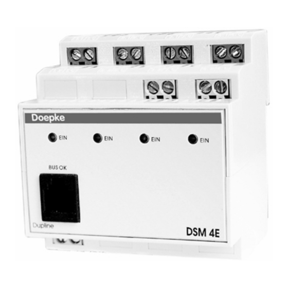
4-fach Relaisausgabe DSM 4E
Inhaltsverzeichnis
1. Allgemeines.............................. 2
2. Kodierung................................. 2
3. Inbetriebnahme ........................ 2
4. Anzeigen .................................. 3
5. Technische Daten .................... 3
6. Garantie ................................... 4
13. Anschlussschema / Connection
Diagram.................................... 8
Dupline
mit Halbleitereingängen
4-way Relay Output DSM 4E
with Semiconductor Inputs
Bedienungsanleitung
Operating Instructions
Table of Contents
7. General Information ................. 5
8. Coding ...................................... 5
9. Putting into Service .................. 5
10. Indicators.................................. 6
11. Technical Data ......................... 6
12. Guarantee ................................ 7
Diagram.................................... 8
3931172/02/05/D
Advertisement
Table of Contents

Subscribe to Our Youtube Channel
Related Manuals for Doepke Dupline DSM 4E

Summary of Contents for Doepke Dupline DSM 4E
- Page 1 Doepke Dupline 4-fach Relaisausgabe DSM 4E mit Halbleitereingängen 4-way Relay Output DSM 4E with Semiconductor Inputs Bedienungsanleitung Operating Instructions Inhaltsverzeichnis Table of Contents 1. Allgemeines......2 7. General Information ....5 2. Kodierung......... 2 8. Coding ........5 3. Inbetriebnahme ......2 9.
- Page 2 Doepke Bedienungsanleitung Dupline 4-fach Relaisausgabe DSM 4E 1. Allgemeines Das DSM 4E ist eine Komponente des Dupline-Installationssystems und ermöglicht das Schalten von vier unabhängigen Verbrauchern, die auf verschiedene Phasen aufgeteilt sein dürfen. Jeder Verbraucher darf dabei eine Stromaufnahme von bis zu 16 A aufwei- sen.
- Page 3 Doepke ten. Folgende Tabelle zeigt die Anschlussbelegung: Klemme Beschreibung Klemme Beschreibung 1.1/1.5 Schaltkanal 1 (L 3.2/C5 Halbleitereingang C5 2.1/2.5 Schaltkanal 2 (L 3.6/C6 Halbleitereingang C6 3.1/3.5 Schaltkanal 3 (L 4.2/C7 Halbleitereingang C7 4.1/4.5 Schaltkanal 4 (L 4.6/C8 Halbleitereingang C8 Dupline Signalleiter - (Dupline-)
- Page 4 Doepke Min. Typ. Max. Glühlampen 3000 W HV-Halogenlampen 2500 W Leuchtstofflampen 2400 W Leuchtstofflampen mit EVG 600 W Gasentladungslampen max. 1000 W (70 µF), 1250 W (100 µF Kondensator zur Kompensation max. 70 µF, (100 µF Energiesparleuchten mit KVG 1250 W...
- Page 5 Doepke Operating Instructions Dupline 4-way Relay Output DSM 4E 7. General Information The DSM 4E is a component of the Dupline installation system and permits switching of four independent loads which may be operated using different phases. The current re- quirement of each load may be up to 16 A.
- Page 6 Doepke tors has to be ensured. The following table illustrates the connection configuration: Terminal Description Terminal Description 1.1/1.5 Switching ch. 1 (L 3.2/C5 Semiconductor input C5 2.1/2.5 Switching ch. 2 (L 3.6/C6 Semiconductor input C6 3.1/3.5 Switching ch. 3 (L 4.2/C7...
- Page 7 Doepke Min. Typ. Max. Incandescent lamps 3000 W HV-halogen lamps 2500 W Fluorescent lamps 2400 W Fluorescent lamps with el. ballast 600 W Gas discharge lamps max. 1000 W (70µF), 1250 W (100µF Capacitor for compensation max. 70 µF (100µF Energy-saving lamps, conv.
- Page 8 Doepke 13. Anschlussschema / Connection Diagram L in L ou t L in L out L i n L ou t L in L out 3.2 / C5 3.6 / C6 4.2 / C7 4.6 / C8 Doepke BUS OK...
Need help?
Do you have a question about the Dupline DSM 4E and is the answer not in the manual?
Questions and answers