Advertisement
Quick Links
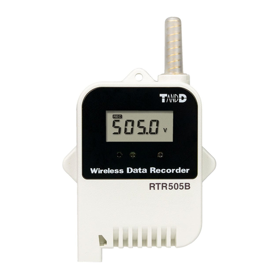
Wireless Data Recorder
RTR505B User's Manual
Thank you for purchasing our product.
To ensure safe and proper operation, please read this guide
thoroughly before use.
Overview
RTR505B is a data logger designed to measure and record
different items depending on the input module to be con-
nected: temperature (Thermocouple, Pt), analog signal
(4-20mA, DC voltage), and pulse.
Recorded data is then automatically collected by the Base Unit via
wireless communication and downloaded for archive and analysis.
RTR505B requires a Base Unit to carry out wireless communication.
(Compatible Base Units: RTR500BC, RTR500BW, RTR500BM, RTR-
500MBS-A, RTR-500DC, RTR-500, RTR-500NW/AW)
For the operation and configuration of the Base Unit, refer to
the instruction manual attached to the Base Unit or the RTR500B
Series Help available on T&D Website.
Wireless Data Recorder RTR505B is referred to as the "(data) logger"
or "device" in this manual.
tandd.com
© Copyright T&D Corporation. All rights reserved.
2020.11 16508210002 (1st Edition) Printed on recycled paper.
Package Contents
• RTR505B or RTR505BL (Large Battery Type)
• Lithium Battery LS14250 (or Large Capacity Battery Kit RTR-500B1 for L type model)
• Strap (Not included with L type model)
• Manual Set (Warranty Included)
Part Names
Antenna
LCD Display
Optical
Communication
Area
Module Jack
<Front>
Input Modules (Sold Separately)
Measurement Item
Input Module
Temperature
Thermocouple Module
(Type K, J, T, S)
(TCM-3010)
Temperature
PT Module
(Pt100, Pt1000)
(PTM-3010)
Voltage Module
Voltage
(VIM-3010)
4-20mA Module
4-20mA
(AIM-3010)
Pulse Input Cable
Pulse
(PIC-3150)
• Before using the pulse input cable, it is necessary to set the measurement item to "pulse
type" in the Remote Unit Settings of the application.
• In order to change the measurement item, initialize the Remote Unit without connecting
the input module and then redo the Remote Unit registration and settings.
<Side>
<Side>
(L type)
<Back>
LCD Displayed Items
Measurement, Unit of Measurement,
Sensor Type, Operational Status
Measurement, Unit of Measurement,
Sensor Type, Operational Status
Measurement, Unit of Measurement,
Operational Status
Measurement, Unit of Measurement,
Operational Status
Measurement, Unit of Measurement,
Operational Status
Make sure that the module is completely
inserted until you hear a "click" sound.
Battery Installation
Recording starts automatically by inserting the battery with the
default or previous settings.
Battery
Cover
Screw
Rubber
Packing
Lithium Battery
Battery Replacement
When it is time for the battery to be
replaced, a battery warning mark will
appear. Please change the battery as
soon as possible if this mark appears.
If you continue to use the logger without changing the battery, the
current temperature and [bAtt] will be displayed alternately and
wireless communication will stop. (Recording will continue.)
• If the battery is further left unchanged, the display will automatically shut
off and all previously recorded data will be lost.
• Although the logger continues to work for a period after the battery has
been removed, leaving the device without a battery until the LCD display
goes blank will cause all recorded data to be lost.
Remote Unit Registration and Settings
Via Software and Optical Communication
Connect the Base Unit to a PC with a USB cable, and place the data
logger face down to align the communication areas as shown below.
RTR500BW,
RTR-500NW/AW
RTR-500DC
Via Mobile App and Bluetooth
When the Base Unit is a RTR500BW, it is possible to make Base
Unit and Remote Unit settings from nearby mobile devices using
Bluetooth.
Default Settings
Recording Mode
Endless
Recording Interval
10 minutes
Recording Start
Immediate Start
Method
• Make sure to use the proper type and
size screwdriver. (Phillips head #1
screwdriver is recommended.)
• Insert the supplied battery with the
tube attached. When using a CR2 lithi-
um battery, the tube is not necessary.
• Before closing the cover, check the
rubber packing for dust or scratches,
as they can reduce the water resis-
tance of the rubber.
• Be sure to completely close the cover.
Make sure not to over tighten the
screws.
• Appropriate Tightening Torque:
20N·cm to 30N·cm (2Kgf·cm to 3Kgf·cm)
Alternating
Display
RTR500BM,
RTR-500MBS-A
RTR500BC,
RTR-500
®
Communication
Advertisement

Related Manuals for T&D RTR505B


Summary of Contents for T&D RTR505B
- Page 1 20N·cm to 30N·cm (2Kgf·cm to 3Kgf·cm) Series Help available on T&D Website. Battery Replacement Wireless Data Recorder RTR505B is referred to as the “(data) logger” or “device” in this manual. When it is time for the battery to be replaced, a battery warning mark will appear.
- Page 2 How to Read the LCD Display Other Indications on Display Logging Capacity FULL When Recording Mode has been set to “One Time” and the logger reaches its logging capacity of 16,000 readings, recording will automatically stop and in the LCD the measurement and the word [FULL] will alternately appear.