Sinclair S-THERM+ SHP-140ECA Owner's Manual
Split air to water heat pumps
Hide thumbs
Also See for S-THERM+ SHP-140ECA:
- Control and operation manual (68 pages) ,
- Service and installation manual (62 pages)

Related Manuals for Sinclair S-THERM+ SHP-140ECA


Summary of Contents for Sinclair S-THERM+ SHP-140ECA
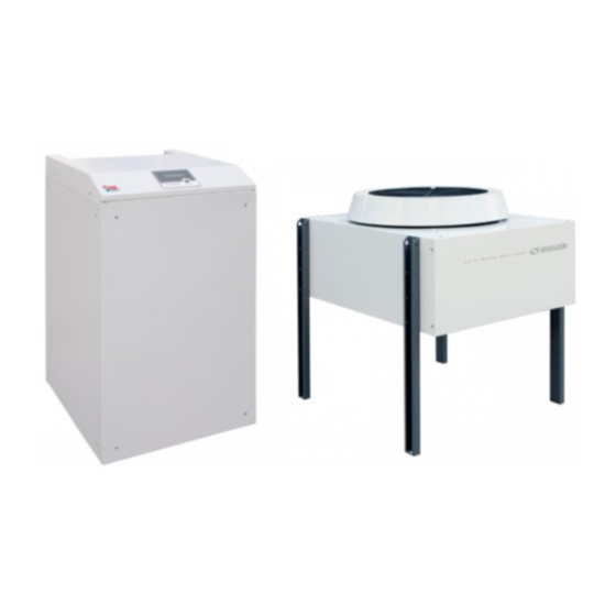
- Page 1 OWNER’S MANUAL SPLIT AIR TO WATER HEAT PUMPS SHP-140ICA + SHP-140ECA H E A T U M P S...
-
Page 2: Table Of Contents
Contents Basic information ............................2 Cautions and Warnings ..........................3 Safety precautions ............................7 Transportation .............................. 8 Inspection and storage ..........................8 Product description ............................9 House heating and hot water supply ......................10 Heat pump functions ........................... 10 Specifications ............................. 11 Packing............................... -
Page 3: Basic Information
Operation of SINCLAIR S-THERM+ heat pump system is thus much more stable. High temperature heat pump SINCLAIR S-THERM+ and its control unit was designed as a complex system providing efficient management of thermal energy to guarantee balanced and efficient operation of a house, inclusive integration of solar cells as a additional source of thermal energy and a possibility for swimming pool heating. -
Page 4: Cautions And Warnings
Safety Where children or persons with limited physical, sensory or mental capabilities are to be allowed to operate this equipment, ensure that this will only happen under supervision or after appropriate training by a person responsible for their safety. Children should be supervised to ensure that they do not play with the equipment. - Page 5 Remarks to icons Icon Meaning Subject of prohibition is indicated next to the icon. Prohibition! Indicated action must be done. Mandatory action! Follow given instructions. Warning! Warning Icon Meaning If you find there is a fault or abnormal behavior of the unit, stop operation and switch off by disconnecting power cable from the socket, or by switching off main switch or circuit breaker.
- Page 6 Do not insert your fingers or other objects into indoor or outdoor unit, rotating parts could cause an injury. PROHIBITION Do not put any objects on the unit or directly under it. PROHIBITION Transport and repairs Meaning If it is necessary to move the unit or to make a new installation, please ask for help your supplier or a qualified person.
- Page 7 If power cable is damaged, it must be replaced by a qualified person in order to avoid a risk of electrical shock. Power supply cable Unit must have a good earth connection, otherwise there is a risk of electrical shock or fire. Earth connection Operation Meaning...
-
Page 8: Safety Precautions
Safety precautions 1) Prevention of explosion and fire Some parts of heat pump (indoor unit) can become very hot. Do not touch any pipes of heating system which have no thermal insulation. Do not remove any parts of casing. 2) Prevention of frostbites Supplied heat pump (indoor unit) is charged with refrigerant R407c. -
Page 9: Transportation
Transportation Please transport the unit always in the upright position. Do not lay it on its side, otherwise some internal parts could be damaged. During transportation and loading down avoid any sudden movements. When moving, touch the unit always on its base part. When using a fork lift, use always a protective block between the forks so that there is no damage to the unit and its covers. -
Page 10: Product Description
Product description The air-source heat pump extracts heat from outdoor air and transfers it into water. Heat pump systems consist of separated circuits, where heat is transferred from its source to the heating system using liquids or gases. As these circuits use different media (air, refrigerant and heating water), circuits are connected through heat exchangers. -
Page 11: House Heating And Hot Water Supply
Heat pump is equipped with an intelligent control system with the possibility of controlling up to 18 switch relays with the capacity of 230V/2A max. Besides this, the system can control two step motors of expansion valves and the control board has two outputs with voltage 0 to 10V for exchanger fan speed control or heat pump compressor control. -
Page 12: Specifications
Specifications Below given values are only informative. Actual specifications can be found on nameplate of the unit. Heat pump system can be operated under all rates of electric energy consumption. Outdoor unit SHP-140ECA Model Indoor unit SHP-140ICA Capacity* 14,18 Power input* 3,10 COP* 4,56... -
Page 13: Packing
Outdoor unit SHP-140ECA Model Indoor unit SHP-140ICA Outdoor unit dimensions (w*d*h) 1168x1066x1195 Indoor unit dimensions (w*d*h) 597x596x991 Outdoor unit weight Indoor unit weight Acoustic power level L outdoor unit 60,3 Acoustic power level L indoor unit 55,4 Acoustic pressure level L indoor unit v 1 m 41,2 Acoustic pressure level L... -
Page 14: Dimensions And Heat Pump Appearance
Dimensions and heat pump appearance Indoor unit Indoor unit appearance Description Indoor unit provides efficient heat exchange between the refrigerant circuit and the water circuit and is located inside a house or a building. Indoor unit stands on a steel base with four rubber feet. Heat pump components are located inside the indoor unit. - Page 15 Views Dimensions...
-
Page 16: Control Panel
Control panel Dimensions Outdoor unit Outdoor unit appearance Description Outdoor unit (evaporator) is located outside a house or building. Main part of the unit is the evaporator, which is covered from upper side, from back side and from cover sides with metal plates, which are fixed by rivets and therefore are not removable. - Page 17 Views Dimensions Console dimensions...
-
Page 18: Unit Description
Unit description Indoor unit Secondary circuit - water Primary circuit - refrigerant Panel with display Base Covers... -
Page 19: Outdoor Unit
Outdoor unit Fan with motor Feet Evaporator with casing Connections between indoor and outdoor unit Copper pipes Copper pipes are used to connect indoor and outdoor unit. Piping must be installed by specialized company and piping must be as short as possible and with minimum bends. Specialized company will install also communication and power supply cables. -
Page 20: Operation Range
Operation range Capacity specifications CAPACITY SPECIFICATIONS Ambient temperature (A) / Output water temperature (W) (°C) * SHP - 140 Model 14, 17 Corrected heating capacity (kW) Effective electric power input (kW) 3, 10 A7/W35 Heating COP (-) 4, 56 Corrected heating capacity (kW) 8,78 Effective electric power input (kW) 2,29... -
Page 21: Place Of Installation
Place of installation Outdoor unit Outdoor unit can be installed on any place outside, which can carry the weight of this heavy unit as e.g. terraces, terrain etc. Place of installation must be protected against influences of heat or fire. It is recommended to use protective covers or roofs to protect the unit against snow in winter. - Page 22 Indoor unit Place of installation must have a good ventilation. Indoor unit must be installed inside a house or building (cellar, veranda, service or technical room etc.) on a dry place, where unit will be permanently protected against frost and where temperature range of 7°C to 25°...
-
Page 23: Method Of Installation
Method of installation Heat pump can be installed on the floor on a concrete base using spacer screws or on a metal frame using rubber feet. Please ensure the unit is installed horizontally. 1) Prepare a foundation for outdoor unit installation. 2) Build concrete pillars, where feet of the outdoor unit will stand. -
Page 24: Water Connections
Water connections When making water connections, take into consideration remarks below: Heat pump is determined to be connected to a closed system of central heating. In order to guarantee fault-free operation, central heating installation must be made by authorized specialized persons and in accordance with corresponding standards and rules. -
Page 25: Hydraulic Diagram
Hydraulic diagram Basic components of the heat pump Install hydraulic components according to the local requirements analogically to the following examples of hydraulic diagram. (This example of hydraulic diagram does not contain all closing and safety parts, necessary for professional installation.) Version 1: Heat Pump with a Combined stainless flow water heater for DHW located in buffer tank for water for heating circuit. - Page 26 - very compact (we will deliver). The possibility to connect a solar exchanger. b) Small Sinclair heat pump for independent DHW heating either with solar heating or without this. c) Pump Grundfos for water circulation in radiators (if heating with radiators is installed).
-
Page 27: Water Pump
Version 3: Heat Pump with two Separate tanks System consists of accumulation tank for heating system without the possibility of connecting to a solar heating connected with DHW tank with or without the possibility of connecting to a solar water heating. a) Simple buffer tank for heat pump for heating water circuit with the volume of 400, 500, 600L in PU foam insulation - very compact (we will deliver). -
Page 28: Electrical Connections
Electrical connections Before starting the work on electrical connections ensure, the power supply corresponds to the data on manufacturer´s nameplate and check also the electric characteristics of the unit. Important: person making the installation is responsible for connection of unit protective circuit breaker, which must have parameters corresponding to the capacity of the unit (see table with electric characteristics of the unit). -
Page 29: Maintenance And Cleaning
Maintenance and cleaning Indoor unit Before starting the maintenance and cleaning of the heat pump switch always power supply off! WARNING When cleaning the heat pump, do not use thinner, benzene or other aggressive cleaning solutions or powder, do not use water warmer than 40°C. Cleaning can be done with a neutral soap or any non-aggressive common cleaner for the use in the kitchen. -
Page 30: Check Of Filling Pressure Of The Heating System
Danger of injury and damage due to the unauthorized maintenance and repair! WARNING Never try to make repair or maintenance of the heat pump by yourself. PROHIBITION Service engineer should be authorized for this activity. In order to guarantee all functions of S-THERM+ unit permanently and to keep correct and approved working order, only original S-THERM+ spare parts can be used exclusively for maintenance and service work! Check of filling pressure of the heating system Filling pressure of your heating system can be read on the pressure gauge, which was installed as a part of... -
Page 31: Common Faults And Troubleshooting
Common faults and troubleshooting Identify and solve the problem with the help of information below. Problem solving should be done by a qualified service engineer. Problem Possible cause Solution Heat pump 1 Fault in power supply 1 Switch the unit off and check power supply cannot be started 2 Loose power cable 2 Check the power cable and its connection... -
Page 32: Error Messages And Solutions
Error messages and solutions See Operation manual Options 5 pcs temperature sensor in the packing inside the unit. Recycling Heat pump system, all parts of options and transport packing are made mostly from materials, which could be recycled; these parts should not be disposed as a household waste. Environmental hazard in case of unqualified disposal! WARNING Unqualified disposal of refrigerant can cause environment pollution. -
Page 33: Service
SAFETY DATA SHEET R 407C Safety data sheet reworked according to the ANNEX I of Commission Regulation (EU) No 453/2010 SECTION 1: Identification of the substance/mixture Chemical name / Synonym: R 407C / Klea 66 / AC 9000 Trade name: R 407C Usage: Refrigeration... -
Page 34: Safety Data Sheet
Classification of components according to the criteria in Regulation (EC) No 1272/2008 [CLP/GHS]: Classification according to the EC Number Concentration Registry Component name criteria in Regulation (EC) No (EINECS) [% hm.] Number 1272/2008 [CLP/GHS] 811-97-2 213-377-0 1,1,1,2-tetrafluorethane (R 134a) 50 - 54 Gas under pressure, H 280 354-33-6 206-557-8... - Page 35 Environmental precautions: If possible, stop product release. Prohibit release into the environment - drainage, surface water and soil. Using appropriate method enclose the place of release and prohibit expansion (e.g. floating barrages etc.). Leaking gas/vapor/fog spray with water stream. Disposal instructions: Provide sufficient ventilation.
- Page 36 Exposure limitation: Persons: When working with refrigerant, have always breathing mask with proper filter in ready position. Use self-contained breathing apparatus always when entering area with stored refrigerant and do not take off, until you are sure the air in the area is clean. Always use personal protective equipment and respect general rules for work with chemical substances.
- Page 37 SECTION 12: Ecological information Toxicity: Acute toxicity for aquatic organism* LC50, fish: 450 mg/l exposure 96 hours (Oncorhynchus mykiss) EC50, daphnia: 980 mg/l exposure 48 hours (Daphnia magna) EC50, algae: not available EC10, bacteria: > 730 mg/l exposure 6 hours (increase Ps.
- Page 38 SECTION 15: Regulatory information Related regulations: Act no. 356/2003 Coll., in the wording of later regulations and on an amendment to certain other acts Act no. 258/2000 Coll., in the wording of later regulations and on amendments to other acts Act no.
- Page 39 NEPA, SPOL. S R.O., PURKY OVA 45, 612 00 BRNO TEL: +420 800 100 285, FAX: +420 541 590 124 www.nepa.cz, tepelnacerpadla@nepa.cz INSTALLATION PROTOCOL - HANDOVER PROTOCOL After Heat Pump installation please fill in this protocol and send latest within 14 days to the address: Nepa spol.
- Page 40 SINCLAIR CORPORATION Ltd. 1-4 Argyll St. London W1F 7LD Great Britain www.sinclair-world.com This product was manufactured in China (Made in China). REPRESENTATIVE SINCLAIR EUROPE spol. s r.o. Purkynova 45 612 00 Brno Czech Republic TECHNICAL SUPPORT NEPA spol. s r.o. Purkynova 45...
Need help?
Do you have a question about the S-THERM+ SHP-140ECA and is the answer not in the manual?
Questions and answers