
Related Manuals for Sinclair SWH-190-300IRE


Summary of Contents for Sinclair SWH-190-300IRE
- Page 1 INSTALLATION AND OPERATING MANUAL SWH-190-300IRE Heat pumps for domentic hot water M0MR00003-10 20-03-2019...
- Page 2 Dear Customer, We congratulate you on choosing this product For many years Sinclair has been offering systems that provide maximum comfort, together with high reliability, efficiency, quality and safety. The aim of the company is to offer advanced systems, that assure the best comfort, reduce energy consumption and the installation and maintenance cost for the life cycle of the system.
-
Page 3: Table Of Contents
INDEX Before any operation carefully read the GENERAL WARNINGS General instructions Residual risks / Disposal General Reception Installation Water connections Aeraulic connections Electrical connections Start - up Control Maintenance Technical data Pay particular attention to: INSTALLER use USER use WARNING, identifies particularly important operations or information PROHIBITIONS, identifies operations that must not be carried out, that compromises the operating of the unit or may cause damages to persons or things. -
Page 4: General Instructions
1 - GENERAL INSTRUCTIONS It is forbidden to trample on the device USER and/or to put on it any type of object. This appliance can be used by children It is forbidden to throw or spray water aged from 8 years and above and directly on the device. - Page 5 1 - GENERAL INSTRUCTIONS GENERAL INSTRUCTIONS Preliminaries Read carefully the IOM and use the unit strictly according to the instructions in order to avoid personal injuries, damages Children, disabled and elderly are at to the unit, damages to property and highest risk of being scalded.
- Page 6 1 - GENERAL INSTRUCTIONS heating, within limits defined in the ELETTRIC SYSTEM technical bulletin and on this manual. Any use other than intended does not involve the manufacturer in any commitment or obligation. This unit is required reliable earthing before usage, otherwise might cause death or injury.
- Page 7 1 - GENERAL INSTRUCTIONS shown on the serial number label). Verify MODIFICATION that the network has characteristics conforming to the data shown on the All unit modifications will end the serial number label . warranty coverage and the manufacturer Make sure that the unit supply line is responsibility.
-
Page 8: Residual Risks / Disposal
2 - RESIDUAL RISKS / DISPOSAL guarantee adequate anchorage may RESIDUAL RISKS cause the fall or the tipping of the unit with the consequent damage to things, people General or the unit itself. Carefully check the In this section the most common situations positioning and the anchoring of the unit. - Page 9 2 - RESIDUAL RISKS / DISPOSAL and never leave the refrigerating system to removing the protective grill or the fans, taps closed. open the isolator on the attachment line of the unit itself, padlock it and display the Electric parts appropriate warning sign.
- Page 10 2 - RESIDUAL RISKS / DISPOSAL containers by specialised personnel with DISPOSAL the necessary qualifications; • lubrication oil contained in compressors CE WEEE DIRECTIVE and in the cooling circuit to be collected; The manufacturer is registered on the • mixtures with antifreeze in the water EEE National Register, in compliance with circuit, the contents of which are to be implementation of Directive 2012/19/EU...
-
Page 11: General
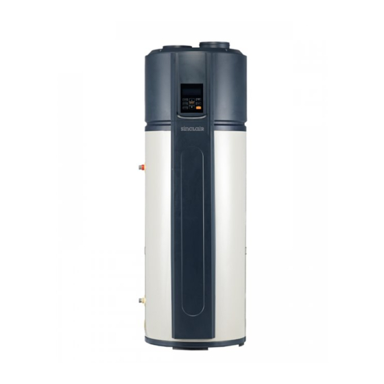
3 - GENERAL UNIT INDENTIFICATION PRELIMINARY INFORMATION Serial number label Before beginning the work, ensure you that have the final The serial number label is positioned on the unit and allows to project for installing the aeraulic, hydraulic, electric,drains and indentify all the unit features. - Page 12 3 - GENERAL PARTS NAMES - 190 Water inlet 3/4” F Air filter Domestic hot water outlet 3/4” F (ACS) Electric panel Sacrificial anode Evaporator Anode cap Compressor Electric heater Rear closure Heating element cap Electrical connector cover Front mask Electrical connections box Front cover A - ATCO (automatic temperature Switch)
- Page 13 3 - GENERAL PARTS NAMES - 300 Water inlet 3/4” F Air filter Domestic hot water outlet 3/4” F (ACS) Electric panel Sacrificial anode Evaporator Anode cap Compressor Electric heater Rear closure Heating element cap Electrical connector cover Front mask Electrical connections box Front cover A - ATCO (automatic temperature Switch)
-
Page 14: Reception
4 - RECEPTION Use protection (A) to avoid the unit damaging 4.1 - DELIVERY CONTROL Before accepting the delivery you have to check: that the unit hasn’t been damaged during transport. Stair climbing trolley. Check that the materials delivered correspond with that indicated on the transport document comparing the data with the identification label ‘A’... - Page 15 4 - RECEPTION 4.3 - PACKAGING REMOVING Be careful not to damage the unit. Keep packing material out of children’s reach it may be dan- gerous. Recycle and dispose of the packaging material in conformity with local regulations. Cut the hoops Front Cut along the joint (A) Rear...
- Page 16 5 - POSITIONING 5.2 - CONSIDER SOUND EMISSIONS 5.1 - INSTALLATION REQUIREMENTS Noise levels could represent an inconvenience if installed in The installation has been implemented by qualified technical personnel only and that the instructions contained in the areas that require extreme silence, example near bedrooms. present manual and the local regulations in force have been adhered to.
- Page 17 5 - POSITIONING Check that the floor can support the weight of the unit in Install the unit in the indoor space, it is not allow to install the operation: unit at the rainy space A - > 287 Kg/m (190) B - >...
-
Page 18: Installation
6 - WATER CONNECTIONS 6.1 - WATER FEATURES 6.3 WATER FILTER (Provided by the customer) The filter is extremely important: it helps to lockout any impuri- Fill the storage tank (DHW) only during the unit start-up. ties in the water and avoid clogging the system and heat ex- If the house is not immediately lived,or the unit is turned off for changer. - Page 19 6 - WATER CONNECTIONS Block the condensate drain pipe with the clip supplied. 6.7 - HYDRAULIC CONNECTIONS Clip DHW outlet Aqueduct inlet Condensate drain Connecting drains The condensate must be disposed in order to avoid damages to people and things. To smoothly drain condensate, the unit should be installed at a horizontal floor.
- Page 20 6 - WATER CONNECTIONS 6.8 WATER SYSTEM PIPING In case of installing the unit at a place where outside temperature below freezing point, insulation must be provided for all hydraulic components. 190-300 Indicative plumbing diagram The system components must be defined by Designer and Installer (ex. expansion tanks, vents, taps, calibration/safety valves etc.) Pressure reducing valve Water treatment devices (water softener, etc.) Filter Y...
-
Page 21: Aeraulic Connections
7 - AERAULIC CONNECTIONS Avoid recirculation of exhaust/return air 7.1 AERAULIC DESIGN CRITERIA Use elbows with a 90° downward bend The dimensioning and the correct execution of the aeraulic Unit 190 connections are critical to ensure the unit operating and an appropriate level of quietness in the served area. - Page 22 7 - AERAULIC CONNECTIONS Air filter In terms of the unit connect with duct reaching to outdoor, a reliable water-resistant measure must be conduct on the duct, Filter installing at the unit inlet. to prevent water from dropping into internal of the unit . In terms of the unit with duct, filter in there must be put on the In case the water entering to internal components of the unit, position of duct inlet.
- Page 23 7 - AERAULIC CONNECTIONS Aeraulic Connections The unit must be installed inside the building, preferably in a technical room or a laundry room or a garage. At any rate, it is always preferable to avoid installing the unit near bedrooms or in rooms that must be protected from noise. Outdoor installation is prohibited, as well as installation in places subject to external weather.
-
Page 24: Electrical Connections
8 - ELECTRICAL CONNECTIONS 8.1 - ELECTRICAL WIRINGDIAGRAM - 190 1A/1B/1D/1F wire comes out from tank,must connect with the corresponding component. Power supply The L,N wires,which get through the zero-phase electricity mutual inductor, must keeping the sam direction during wring, Wiring diagram of tank otherwise, system malfunction inside... - Page 25 8 - ELECTRICAL CONNECTIONS 8.2 - ELECTRICAL WIRINGDIAGRAM - 300 1A/1B/1C/1F wire comes out from tank,must connect with the corresponding component. Power supply The L,N wires, which get through the zero phase electricity mutual inductor, must keeping the same direction during wring, otherwise, system malfunction may caused.
- Page 26 8 - ELECTRICAL CONNECTIONS 8.3 - PCB I/O PORTS DESCRIPTION All electrical operations should be performed by trained personnel having the necessary require- This unit is required reliable earthing ments by the regulations in force and being informed about the risks relevant to these activities. before usage, otherwise might cause death or injury.
- Page 27 8 - ELECTRICAL CONNECTIONS Electric Connection The power supply should be an independent circuit with rated voltage. Power supply circuit should be earthed effectively. Do not use water pipes to earthing connection of the unit The wiring must be performed by professional technicians in accordance with national wiring regulations and this circuit diagram. An all-pole disconnection device which has at least 3 mm separation distance in all pole and a residual current device (RCD) with the rating of above 10 mA shall be incorporated in the fixed wiring Set the electric leakage protector according to the relevant electric technical standards of the State.
-
Page 28: Start-Up
9 - START-UP Check tightening of the conductors: the vibrations caused 9.1 PRELIMINARY INFORMATION by handling and transport might cause loosing . Feed the unit by closing the sectioning device, but leave it If the unit has been tipped during transport, wait at least 2 on OFF hours before starting it up Check the voltage and frequency net values which must... - Page 29 9 - START-UP 9.2 - GENERAL The indicated operations should be done by qualified technician with specific training on the product. Upon request, the service centres performing the start-up. The electrical, water connections and the other system works are by the installer. Agree upon in advance the star-up data with the service centre.
- Page 30 9 - START-UP All piping properly installed and free of leaks. Hydraulic system filled, pressurised and drained Expansion tank checked / filled with nitrogen Condensate and safety valve drains Condensate drain line installation Must be located with access to an adequate drain Condensate drain lines installed and piped to an adequate drain The unit requires 220-240 VAC for proper operation.
- Page 31 9 - START-UP 9.4 - TRIAL-RUNNING 9.4 - CHECKING LIST BEFORE COMMISIONNING 1) Checking list before trial-running. Water effusion before operation 2) Correct installation of the system. Before using this unit, please follow the steps below. 3) Correct connection of water/air piping and wiring;. 4) Condensate draining smoothly well insulation work for all Storage tank water filling: hydraulic part.
- Page 32 9 - START-UP 3) Heat source will be automatically selected by unit. But About TCO and ATCO manually E-Heater operation is available. The power of compressor and E-heater will be automatically shut-off or turn on by TCO and ATCO. 4) Heat Source Shift If the water temperature is higher than 78°C, the ATCO will automatically shut off the power of compressor and E-heater, The default heating source is heat pump.
- Page 33 9 - START-UP 9.6 - BASIC FUNCTION Hour Min. Min. Temp. / Description low bit higt bit low bit Days How is the unit running If unit is OFF, press unit will be waken, press T5U: Storage tank Temp. temperature sensor to set target water temperature (38-70°C), press unit (Upper)
-
Page 34: Control
10 - CONTROL 10.1 - DISPLAY After powered on, the display lights up. Users can operate the unit through the buttons under the display. Display Display icons Function 1 - Outside solar heat source Don't available 2 - Vacation mode (Vacation) Icon will be lightened if the unit is under vacation mode, will flash with 2 sec. - Page 35 10 - CONTROL 5 - Anti-legionella mode (Disinfect) Icon will be lightened when the unit is under disinfect mode, otherwise will be extinguished. Icon will be lightened if disinfect mode is automatically activated by unit; will flash with 0.5 sec frequency, if disinfect mode is manually activated; will flash with 2 sec.
- Page 36 10 - CONTROL 13.1 - Water Temperature setting (SET) Icon SET will be lightened when setting water temperature or setting days for vacation. 13.2 - Date setting (Day) Icon DAY will be lightened when setting days for vacation; Icon DAY will be lightened when under vacation mode. 14 - Programmes (Timer) There are six timers can be set.
- Page 37 10 - CONTROL 2 - Increase / up If screen is unlocked, corresponding value will increase by pushing When setting temperature, press more than 1sec., temperature value will be increased continuously When Setting clock/timer, press more than 1sec., clock/timer value will be increased continuously When setting vacation days, press more than 1sec., day value will be increased continuously Under query mode, check items will page up by pressing 3 - Set Clock...
- Page 38 10 - CONTROL The display screen will automatically display different value at by different action. It will display the last set temperature and icon SET ,if the action is ON, and will display - - - if the action is OFF. Set the water temperature of the setting timer.
- Page 39 10 - CONTROL 5 - Start-up/shutdown button and LED indicator If unit is standby, press Then unit will be OFF. If unit is ON, press Then unit will be OFF. If unit is OFF, press Then unit will be ON. LED indicator will be lightened if unit is ON or standby and extinguished if unit is OFF.
- Page 40 10 - CONTROL Icon ‘ ’ will flash, and icon will be lightened and the hour value of clock will flash slowly. Set the hour Confirm the hour setting. Then the minute value of clock will flash slowly. Set the minutes Confirm the disinfect clock setting and quit out.
- Page 41 10 - CONTROL 10.3 AUTO-RESTART 10.6 SOMETHING ABOUT SELF-PROTECTION OF UNIT If electricity power failed, unit can memorize all setting parameters, unit will be back to the previous setting when When the self-protection happens, the system will be stopped power recover. and start self-check, and restart when the protection resolved.
- Page 42 10 - CONTROL 10.8 ALARMS Description Solution Code Maybe the connection between sensor and PCB has released Error of sensor T5U (upper water temperature sensor) or sensor has been broken. Contact a qualified person to service the unit. Maybe the connection between sensor and PCB has released Error of sensor T5L(lower water temperature sensor) or sensor has been broken.
- Page 43 10 - CONTROL 10.8 ALARMS Code Description Solution System high pressure protection: Maybe because of system blocked, air or water or more Unit 300 : >=3.0Mpa active; <=2.4MPa inactive. refrigerant in system (after repair), water temperature sensor malfunction, ect. Unit 190 : P1 error code never appear because pressure Contact a qualified person to service the unit.
- Page 44 10 - CONTROL 10.9 NON-ERROR TIPS Q: Why compressor can't start immediately after setting? A: Unit will wait for 3 min to balance the pressure of system before start compressor again, it's a self protection logic of unit. Q: Why sometimes the temperature shown on the display panel decreased while unit is running? A: R.
-
Page 45: Maintenance
11 - MAINTENANCE 11.1 CHECKLIST FOR RECOMMENDED REGULAR CHECKS Disconnect the power supply before each operation. Checks effected on…………………...…………..by…………………………...…...……………………….of the company…………………………………….. Checking content Checking frequency Action Air filter (inlet/outlet) Every month Clean the filter Anode Every 6 - 12 months Replace it if it has been used out Inner storage tank Every half year... - Page 46 11 - MAINTENANCE 11.2 GENERAL 11.5 PUT AT REST In some cold areas (under 0°C), if the system will be stopped Maintenance must be done by authorized centres or by for a long time, empty the storage storage tank in order to qualified personnel avoid the water freezing and damage of E-heater.
- Page 47 11 - MAINTENANCE 11.9 EXPANSION TANK Check the expansion vessel charge (at least once a year). First check that the expansion vessel is totally drained of water. If you necessary load with nitrogen, take care that the pressure does not exceed the value indicated on the label. 11.10 ANODE ROD REPLANCE The magnesium sacrificial anodes assure the storage tank anti-corrosive protection.
- Page 48 11 - MAINTENANCE 11.11 STORAGE TANK EMPTYING 11.13 FILTER CLEANING The air filter blocks dust. If the unit needs cleaning, moving etc, the storage tank should If the filter is blocked, the unit will not work as well. be emptied. The operating with clogged filters leads to a reduction of the air flow, leading to malfunctions and unit shutdowns.
- Page 49 11 - MAINTENANCE 11.14 REPLACE OR CONTROL THE ELECTRIC HEATER If the replace or control of the electric heater Remove power supply Remove frontal cover (A) Unscrew the screws and remove the cover cap (B) Turn off the water inlet valve (C) Open hot water tap for decrease the pressure of the storage tank.
-
Page 50: Technical Data
12 - TECHNICAL DATA DIMENSIONAL Compressor compartment Functional spaces Air supply Electric panel Magnesium anode Unit keypad Water inlet 3/4” F Electric line input Water outlet 3/4”F Condensate drain Air inlet Size Operating weight Shipping weight Shipping height 2070 Shipping depth Shipping width... - Page 51 12 - TECHNICAL DATA DIMENSIONAL Compressor compartment Functional spaces Air supply Electric panel Magnesium anode Unit keypad Water inlet 3/4” F Electric line input Water outlet 3/4”F Condensate drain Air inlet Size Operating weight Shipping weight Shipping height 2200 Shipping depth Shipping width...
- Page 52 12 - TECHNICAL DATA GENERAL TECHNICAL Size Power and Efficiency Thermal power 1,62 2,30 Tout 15/12°C ( DB/WB), Tw,in 15 °C Total power absorbed 0,42 0,53 Tw,out 45°C 3,86 4,34 Thermal power 2,31 3,25 Tout 43/26°C ( DB/WB), Tw,out 70°C --> 190 Total power absorbed 0,546 0,627...
- Page 53 12 - TECHNICAL DATA Size Ventilation Type of fan Centrifugal Air flow Available pressure head 1. Inlet water temperature 15 °C, accumulator set 45°C, air on source side 15°C D.B /12°C W.B. 2. The product complies with the European Directive ErP, which includes the Commission Delegated Regulation (EU) N. 812/2013 and the Commission Delegated Regulation N. 814/2013, Average Climate, Heat Pump Water Heater 3.
- Page 57 NOTE...
- Page 58 NOTE...
- Page 59 NOTE...
- Page 60 SINCLAIR CORPORATION Ltd., 1-4 Argyll St., London, UK...
Need help?
Do you have a question about the SWH-190-300IRE and is the answer not in the manual?
Questions and answers