Table of Contents
Advertisement
Quick Links
rev. 1/16/2017
Receiving Instructions:
After delivery, remove the packaging from the product. Inspect the product closely to determine whether it
sustained damage during transport. If damage is discovered, record a complete description of it on the bill of lading.
If the product is undamaged, discard the packaging.
NOTE:
Compliance with laws, regulations, codes, and non-voluntary standards enforced in the location where the product
is used is exclusively the responsibility of the end-user.
Table of Contents
Signal words............................................................................................................................................................ 2
Improper use might cause personal injuries........................................................................................................... 2
Specifications................................................................................................................................................... 3
Diagram of Hydraulic System.............................................................................................................................. 3
FIG. 1: CBS-64-1 (AC & DC) exploded parts diagram & parts list.................................................................................... 4
FIG. 2: CBS-76-1 (AC & DC) exploded parts diagram & parts list................................................................................5
FIG. 3: 115VAC modular power unit electrical circuit diagram..................................................................................... 6
FIG. 4: 12VDC modular power unit electrical circuit diagram...................................................................................... 6
FIG. 5: 3-phase AC modular power unit diagram..................................................................................................... 7
FIG. 6: Single phase 208 / 230 VAC modular power unit diagram................................................................................. 7
FIGS. 7A & 7B: 12VDC modular power unit layout (parts 1 & 2).................................................................................. 8 - 9
FIG. 8: AC modular power unit layout.................................................................................................................... 10
FIG. 9: DC modular power unit exploded parts diagram............................................................................................ 11
FIGS. 10A & 10B: AC modular power unit exploded parts diagram.............................................................................. 12-13
Loading Instructions.......................................................................................................................................... 14
Hydraulic system.............................................................................................................................................. 14
DC-Powered hydraulic system troubleshooting guide............................................................................................... 15-16
Battery charger operation................................................................................................................................... 17
Inspections & Maintenance............................................................................................................................................ 18
Labeling diagram.............................................................................................................................................. 19
Limited warranty............................................................................................................................................... 20
Copyright 2017 Vestil Manufacturing Corp.
2999 North Wayne Street, P.O. Box 507, Angola, IN 46703
Telephone: (260) 665-7586 -or- Toll Free (800) 348-0868
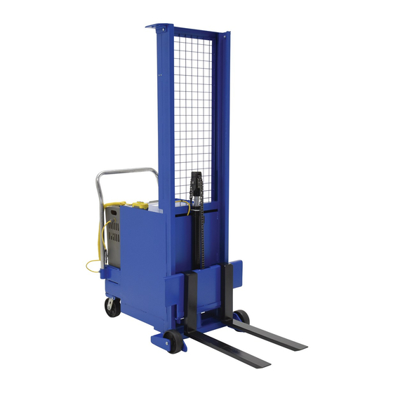
CBS-Series Counterbalanced Stackers
Instruction Manual
CBS, MANUAL.doc
V
M
ESTIL
ANUFACTURING
Fax: (260) 665-1339
www.vestilmfg.com
C
.
ORP
e-mail:
sales@vestil.com
Page 1 of 20
Advertisement
Table of Contents

Related Manuals for Vestil CBS Series


Summary of Contents for Vestil CBS Series
-
Page 1: Table Of Contents
FIGS. 10A & 10B: AC modular power unit exploded parts diagram…………………………………………………………………... 12-13 Loading Instructions………………………………………………………………………………………………………………………… 14 Hydraulic system……………………………………………………………………………………………………………………………. 14 DC-Powered hydraulic system troubleshooting guide………………………………………………………………………………….. 15-16 Battery charger operation………………………………………………………………………………………………………………….. 17 Inspections & Maintenance……………………………………………………………............... 18 Labeling diagram…………..……………………………………………………………………………………………………………….. 19 Limited warranty…………………………………………………………………………………………………………………………….. 20 Copyright 2017 Vestil Manufacturing Corp. Page 1 of 20... -
Page 2: Signal Words
Read the manual to refresh your understanding of proper use and maintenance procedures. DO NOT modify the product in any way UNLESS you first obtain written approval from Vestil. Unauthorized modifications might make the lift unsafe to use and automatically void the Limited Warranty (see p. 20). -
Page 3: Specifications
540 kg 1,000 lb. 3” x 25 ” x 1” 91 in. 83½ in. 1,189 lb. CBS-76-1-AC ~454 kg 7.6cm x 64.8 cm x 2.5cm 231 cm 212 cm 540 kg Copyright 2017 Vestil Manufacturing Corp. Page 3 of 20... - Page 4 99-021-927 Cylinder, telescopic, 28” stroke 37030 ” – 13 nylon insert lock nut 21-527-005 Pulley subassembly 36209 ” – 13 hex jam nut, plain 42034 U-bolt, zinc plated, ” – 18x2” pipe size Copyright 2017 Vestil Manufacturing Corp. Page 4 of 20...
- Page 5 ” rod x 42” stroke 16-132-354 Caster wheel, GFN-6/2-W 10 16-132-261 Caster, GFN-6/2-SWW 21-542-004 Chain subassembly Machine bushing, low carbon, plain Nylon insert lock nut, grade 2, zinc 11 33424 37024 finish, ”x18ga. finish, ”–16 Copyright 2017 Vestil Manufacturing Corp. Page 5 of 20...
- Page 6 FIG. 3: 115VAC Modular power unit electrical circuit diagram Drawing no. 99-124-026, Rev. D Disconnect power before working on the FIG. 4: 12VDC Modular power unit electrical circuit diagram power unit! Drawing no. 99-124-026, Rev. D Copyright 2017 Vestil Manufacturing Corp. Page 6 of 20...
- Page 7 Disconnect power before working on the power unit! Drawing no. 99-124-032 FIG. 6: Single Phase 208/230VAC Modular Power Unit Diagram Disconnect power before working on the power unit! Drawing no. 99-124-033 Copyright 2017 Vestil Manufacturing Corp. Page 7 of 20...
-
Page 8: Figs. 7A & 7B: 12Vdc Modular Power Unit Layout (Parts 1 & 2)
1/16/2017 CBS, MANUAL.doc Drawing no. 99133001 rev. A Copyright 2017 Vestil Manufacturing Corp. Page 8 of 20... - Page 9 1/16/2017 CBS, MANUAL.doc Drawing no. 99133002 rev. A Copyright 2017 Vestil Manufacturing Corp. Page 9 of 20...
- Page 10 1/16/2017 CBS, MANUAL.doc Drawing no. 99133003 rev. A Copyright 2017 Vestil Manufacturing Corp. Page 10 of 20...
- Page 11 1/16/2017 CBS, MANUAL.doc FIG. 9: DC Modular Power Unit Exploded Parts Diagram Detail view of item 24 (manifold) Copyright 2017 Vestil Manufacturing Corp. Page 11 of 20...
-
Page 12: Figs. 10A & 10B: Ac Modular Power Unit Exploded Parts Diagram
1/16/2017 CBS, MANUAL.doc FIG. 10A: Detail View of Items 2 and 12 on p. 13 Copyright 2017 Vestil Manufacturing Corp. Page 12 of 20... - Page 13 1/16/2017 CBS, MANUAL.doc FIG. 10B: AC Modular Power Unit Exploded Parts Diagram Copyright 2017 Vestil Manufacturing Corp. Page 13 of 20...
-
Page 14: Loading Instructions
As soon as the descent speed exceeds a preset speed, the velocity fuse activates to cease oil flow. Consequently, the forks will not lower until hydraulic pressure is reestablished. Always unload the forks if the velocity fuse activates. Copyright 2017 Vestil Manufacturing Corp. Page 14 of 20... -
Page 15: Dc-Powered Hydraulic System Troubleshooting Guide
Correct as necessary. Foreign material in flow control valve. Remove and clean flow control valve. Refer to Hydraulic System Diagram on p. 14). x. Binding cylinders. Align cylinders correctly. Copyright 2017 Vestil Manufacturing Corp. Page 15 of 20... - Page 16 To unlock, re-pressurize the hydraulic present in the hydraulic system causing the system. velocity fuse to activate and shut off the oil flow from the cylinders. Consequently, deck will not lower. Copyright 2017 Vestil Manufacturing Corp. Page 16 of 20...
-
Page 17: Battery Charger Operation
3) Check the fuse. Replace only with a fuse having the same rating as originally supplied. 4) Determine battery condition. It may take some time before current begins to flow through a highly sulfated battery. Copyright 2017 Vestil Manufacturing Corp. Page 17 of 20... -
Page 18: Inspections & Maintenance
Step 2: Perform a monthly inspection. If deformity, corrosion, rusting, or excessive wear of frame members is noticed, DO NOT continue to use the stacker. Contact Vestil for instructions. If the fork carriage does not move smoothly or makes noise as it moves up or down the mast, apply a silicon wax or silicon spray to the inside of the mast frame. -
Page 19: Labeling Diagram
C: Label 287 A: Label 220 B: Label 208 D: Label 295 E: Label 527 F: Label 206 Applied to outside of MPU Applied to outside of MPU housing housing G: Label 212 Copyright 2017 Vestil Manufacturing Corp. Page 19 of 20... -
Page 20: Limited Warranty
(you) for warranty service. Who may request service? Only a warrantee may request service. You are a warrantee if you purchased the product from Vestil or from an authorized distributor AND Vestil has been fully paid.
Need help?
Do you have a question about the CBS Series and is the answer not in the manual?
Questions and answers