Table of Contents

Subscribe to Our Youtube Channel
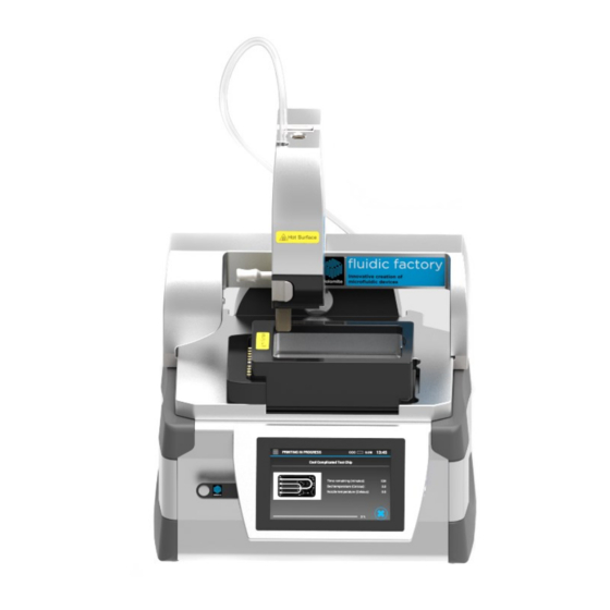
Related Manuals for Dolomite Fluidic Factory


Summary of Contents for Dolomite Fluidic Factory
- Page 1 Fluidic Factory 3D Printer Fluidic Factory USER MANUAL USER MANUAL Version: 1.3 Author: AM MAR-000276_v.1.3 Page 1 of 48 Version: 1.0 Date: 16/03/2016 Chapter: Introduction Author: AM Part Number MAR-000276 Date: xx/xx/2016 P/N: xxxxxxx...
-
Page 2: Table Of Contents
Quick Start Guide .......................... 15 Installing and running the Fluidic Factory ..................15 Assembly Instructions ......................17 4.1.1 Attaching the Print Head to the Fluidic Factory ............. 17 4.1.2 Fitting the Heated Print Bed and Insert ................. 19 4.1.3 Fitting the Filament Coil, Holder Guide and Nozzle ............20 Attaching the Gearbox ...................... - Page 3 Support ............................43 Servicing ..........................43 Cleaning ..........................43 FAQ ............................43 Appendices............................ 44 Appendix A Technical Specifications ..................44 Appendix B Error Codes ....................... 45 MAR-000276_v.1.3 Page 3 of 48 Chapter: Introduction...
-
Page 4: Introduction
Only suitably qualified and trained personnel should operate this unit. Fluidic Factory is not only the world's first COC printer, but is also the first printer able to fabricate fluidically sealed devices. Fluidic Factory uses FDM (fused deposition modelling) method to melt the polymer at high temperatures, eject it through the nozzle onto the print bed and let it solidifies at temperatures below 75°C. - Page 5 Figure 1 illustrates how the chip is built up in a series of layers and how the squashed bead forms a fluidically sealed channel Figure 1 Features are created by adding layers with an obround cross sectional area ("cylinder" with flattened, parallel top and bottom and semi-cylindrical sides). As adjacent layers are printed, the polymer flows into the areas above and below the semi-cylindrical layers to create one seamless layer MAR-000276_v.1.3...
- Page 6 Why Use COC? COC (cyclic olefin copolymer) has a number of unique properties that make it an excellent material for printing microfluidic chips: FDA approved Optically transparent Non-auto fluorescent Excellent resistance towards water-soluble chemicals, acids, alkalis and alcohols ...
-
Page 7: Safety
Do not cover the Fluidic Factory during use. Place the Fluidic Factory on a solid horizontal surface. Ensure the area around the unit is clear. In the case of accidental spillage, carefully wipe with a dry cloth, taking into account the nature of the spilled liquid and the necessary safety precautions. - Page 8 Always connect the Fluidic Factory to an earthed AC power outlet. The operating voltage is indicated on the specification sticker. Non observance of this provision may result in damage to the Fluidic Factory or in personal injury or damage to property.
-
Page 9: Using The Fluidic Factory
3 Using the Fluidic Factory 3.1 Overview Print Head Release and Fitting Catch Filament Guide Print Head Gearbox Induction Print Bed Insert Heater Heated Print Bed On/off Button USB Socket Tap Screen Figure 2: Front View MAR-000276_v.1.3 Page 9 of 48... - Page 10 Filament Tensioning Filament Reel Holder Position Mains Socket and Power Switch Sockets for Service Personnel only Figure 3: Rear View MAR-000276_v.1.3 Page 10 of 48 Chapter: Using the Fluidic Factory...
- Page 11 Print Head Release Filament Guide and Fitting Catch Interface Plate Filament Guide Holder Cooling Fan Print Nozzle Filament Tensioning Arm Gearbox Release Catch Induction Heater Figure 4: Print Head View MAR-000276_v.1.3 Page 11 of 48 Chapter: Using the Fluidic Factory...
- Page 12 Figure 5 below shows the interface at the Home Screen position. Clock and Date Adjust Tools Selector Filament Length Indicator Recent External Samples Storage Print Design Files Figure 5: Home Screen Interface MAR-000276_v.1.3 Page 12 of 48 Chapter: Using the Fluidic Factory...
-
Page 13: Box Contents
3.2 Box Contents When you open the box containing your Fluidic Factory, ensure that you have all of the following parts, as shown in Figure 6 below. Component Image Core unit (Part Number: 3200524) Print head (Part Number: 3200503) Gearbox MAR-000276_v.1.3... - Page 14 Filament Reel Holder Filament Reel Holder (Part Number: 3200501) Heated Print Bed (Part Number: 3200502) Print Bed Insert (x 2) (Part Number: 3200525) Country Specific Power Cord Figure 6 MAR-000276_v.1.3 Page 14 of 48 Chapter: Using the Fluidic Factory...
-
Page 15: Quick Start Guide
Fit the clean Print Bed Insert into the Heated Print Bed where it is magnetically held, then clip it onto the Fluidic Factory Core Unit (see section 4.1.2) Slide the Filament Coil/Filament Coil holder onto the rear of the Fluidic Factory ensuring the Filament Guide is secured into the Filament Coil Holder. (see section 4.1.3) MAR-000276_v.1.3... - Page 16 Gearbox clockwise pushing firmly on the bottom left corner of the Gearbox to lock it into place. Release the arm.(see section 4.1.4) Power up the Fluidic factory by pressing the Power Switch at the rear of the unit then triggering the On/Off Button on the side of the screen (see section 4.1.5) ...
-
Page 17: Assembly Instructions
If a chip design is not yet loaded on the Fluidic Factory, convert chip .stl designs to .phff format using the Fluidic Factory PC software, then export the design files to a USB memory stick (see section 6.2) ... - Page 18 With the Fluidic Factory disconnected from the mains electricity, the Print Head can be fitted. Check that the Interface Plate on the core Fluidic Factory is in its upper position. If it is not already, manually pull the Interface Plate upwards until the Release Catch is above the case work as shown.
-
Page 19: Fitting The Heated Print Bed And Insert
Ensure that the Print Head is fully engaged once the Release and Fitting Catch has been released. See Figure 11. Figure 11 4.1.2 Fitting the Heated Print Bed and Insert Fit the Print Bed Insert into the Print Bed with the handle on the right facing away from the electrical contacts. -
Page 20: Fitting The Filament Coil, Holder Guide And Nozzle
4.1.3 Fitting the Filament Coil, Holder Guide and Nozzle CAUTION: The filament is slightly brittle, please handle any of the components that are in contact with the filament with care, to avoid breakage. If the filament does break, follow the instructions in section 5.8 ... - Page 21 The Print Nozzle is supplied attached to the Filament Guide. Pull back the Filament Tensioner Arm and push the Print Nozzle as far as it will go into the recess but without forcing it. Release the arm. See Figure 19 and 20. Figure 19 Figure 20 ...
-
Page 22: Attaching The Gearbox
Figure 25 Figure 26 4.2.1 Powering up the Fluidic Factory Power up the Fluidic Factory with the Power Switch at the rear of the unit. See Figure 27. Figure 27 MAR-000276_v.1.3 Page 22 of 48 Chapter: Quick Start Guide... - Page 23 NOTE: In day to day use, the Power Switch at the rear can be left on using the On/Off button on the side to complete the power cycle. If moving the location of the Fluidic Factory, also power done at the rear of the Fluidic Factory before disconnecting the power cord.
-
Page 24: Operating The Fluidic Factory
5 Operating the Fluidic Factory On the home screen, you have 4 areas that you can access; Date and Time Settings Recent Samples External Storage Tools 5.1 Date and Time Settings Tap the “Date and Time Settings” to access this menu (see Figure 4.) Change the Day, Month and Year with the roller wheels... -
Page 25: External Storage
5.3 External Storage Print designs can be stored on a USB stick and transferred to the Fluidic Factory via the USB port on the front left of the instrument. See Figure 33. Tap the “External Storage” tab to access this menu. -
Page 26: Move Printer To Cleaning Position
Figure 37 Figure 37 NOTICE: It is very important that the calibration is performed if as indicated. Failure to do this will result in damage to the Fluidic Factory or poor print quality of the chips. MAR-000276_v.1.3 Page 26 of 48... -
Page 27: Detach Print Head From Printer
Figure 40 The next screen is displayed indicating that the print head can be removed. Tap “Print Head Removed” once this has been done. See Figure 41. Figure 41 Figure 41 MAR-000276_v.1.3 Page 27 of 48 Chapter: Operating the Fluidic Factory... -
Page 28: View Application Logs
5.5 Starting a Print Run Prior to a print run, ensure that; The Print Bed and Insert are fitted and clean. The Fluidic Factory is calibrated. The Filament Coil is fitted with the Filament Guide. The Print Nozzle is in place. -
Page 29: Aborting A Print Run
Tap the arrow to start the print run. See Figure 45. Figure 45 Figure 45 To enable printing of new chips, design files must be converted to Fluidic Factory format and NOTE: uploaded into the Fluidic Factory. During the run, live information about the remaining print time, bed temperature and nozzle temperature will be displayed. -
Page 30: Changing The Coc Filament Reel
Support the Gearbox from underneath and rotate anti- clockwise. See Figure 50. Figure 50 Once it has rotated as shown, lower the Gearbox and set aside. See Figure 51. Figure 51 MAR-000276_v.1.3 Page 30 of 48 Chapter: Operating the Fluidic Factory... - Page 31 Filament Coil from the holder. The empty reel should be disposed of. See Figure 53. Figure 53 NOTICE: The black Filament Reel Holder must be retained for repeated use. Fluidic Factory cannot be used without this part MAR-000276_v.1.3 Page 31 of 48...
-
Page 32: Recovering A Broken Filament
Figure 55 NOTICE: The label on the centre of the Filament Reel has an embedded microchip. It is important that is not removed as it contains important information that the Fluidic Factory requires. Fit the Print Nozzle, Filament Guide and Gearbox as described in section 4.1.3 and 4.1.4... - Page 33 Continue to push the COC until it can be seen oozing from the bottom of the Print Nozzle. Remove the melted COC with forceps/tweezers. See Figure 60. Figure 60 MAR-000276_v.1.3 Page 33 of 48 Chapter: Operating the Fluidic Factory...
-
Page 34: Creating New Print Files
Library. Designs can also be created by CAD software and then saved as a .stl file, which carries information about the surfaces of the model. The Fluidic Factory PC software accepts .stl files and outputs print files (.phff). This software is supplied with the Fluidic Factory. Alternatively, a copy can be obtained from Support@dolomite-microfluidic.com. - Page 35 Confirm that the installation should commence. See Figure 64. Figure 64 The installation will continue. See Figure 65. And complete. See Figure 66. Figure 65 Figure 66 MAR-000276_v.1.3 Page 35 of 48 Chapter: Creating New Print Files...
-
Page 36: Using The Pc Software
Place/Review Design: Select the print position on the Print Bed and review the design Review Print Path: visualise the path the Fluidic Factory will take to print the chip. Export: Transfer the .phff file to a storage location on your PC or onto a USB stick for transfer to the Fluidic Factory. - Page 37 Select the print options as required and click “Next”. See Figure 67. Figure 67 The .stl file may take several minutes to convert depending on the size of the file. See Fi Figure 68 MAR-000276_v.1.3 Page 37 of 48 Chapter: Creating New Print Files...
-
Page 38: Place/Review Design
6.2.2 Place/Review Design If any warnings or errors are found, they will be displayed at this in this tab. Errors will be explained NOTE: further in Section 6.2.5. The individual layers can be reviewed by scrolling through the “View Layer” field. ... -
Page 39: Review Print Path
6.2.3 Review Print Path The print paths of the individual layers can now be reviewed. The print path cannot be changed as the optimal print path is calculated by this software. NOTE: Click on the next button to go to the “Export File” tab. See Figure 70 Figure 70 6.2.4... -
Page 40: Errors
Press “Export to choose the save file path location. See Figure 71. Figure 71 6.2.5 Errors Errors can be split into 2 categories, minor and major. Chips with minor errors will warn that there are design errors but the run will still be printed. - Page 41 An example of a minor error is shown in Figure 72. Figure 72 Major Errors An example of a minor error is shown in Figure 73. In this particular circumstance, the size of the chip is too large for the print bed and is remedied by choosing another .stl file or by changing the “Scaling Factor (%)”...
- Page 42 Figure 73 For a full list of errors, common error sources and fixes, see Appendix C. NOTE: MAR-000276_v.1.3 Page 42 of 48 Chapter: Creating New Print Files...
-
Page 43: Support
7.2 Cleaning All surfaces of the Fluidic Factory and should be kept free of dust and fibres. Disconnect the Fluidic Factory from the mains power supply before cleaning and also ensure that is completely cool. The surfaces can be cleaned with a lint free wipe and a small amount of isopropanol. -
Page 44: Appendices
8 Appendices 8.1 Appendix A Technical Specifications Fluidic Factory Specifications Size 300 x 300 x 500 mm Weight 10 kg Printing resolution (dimensions of layer) Fine printing mode: 320 µm (w) x 150 µm (h). Increased operating pressure and greater fluidic sealing Fast printing mode: 400 µm (w) x 200 µm... -
Page 45: Appendix B Error Codes
8.2 Appendix B Error Codes Error Description Action Code Required Requires homing Restart, contact support@dolomite- microfluidics.com if this problem persists Timed out homing X axis Restart, contact support@dolomite- microfluidics.com if this problem persists Timed out homing Y axis Restart, contact support@dolomite- microfluidics.com... - Page 46 Z bed probes are too inconsistent Check that the bed is correctly fitted The memory buffer on the motor control Restart, contact board is unexpectedly full support@dolomite- microfluidics.com if this problem persists The motor control board temperature is Restart, contact...
- Page 47 See Section Extruder motor has stalled Check and remove any build-up of COC Extruder board gone over Restart, contact temperature support@dolomite- microfluidics.com if this problem persists Extruder motor has gone into error Restart, contact support@dolomite- microfluidics.com if this problem persists...
- Page 48 MAR-000276_v.1.3 Page 48 of 48 Chapter: Appendices...
Need help?
Do you have a question about the Fluidic Factory and is the answer not in the manual?
Questions and answers