Table of Contents
Advertisement
Quick Links
SERVICE MANUAL
Ver 1.3 2000.2
With SUPPLEMENT (9-923-270-82)
AUDIO POWER SPECIFICATIONS
POWER OUTPUT AND TOTAL
HARMONIC DISTORTION
With 3-ohm load, both channel driven from
150 - 15,000 Hz; rated 3 W per channel-
minimum RAM power, with no more than
10 % total harmonic distortion in AC
operation.
Other Specifications
CD player section
System
Compact disc digital audio system
Laser diode properties Material: GaALAs
Wave length : 780 nm
Emission duration: Continuous
Laser output: Less than 44.6 µW (This output is
the value measured at a distance of about 200 mm
from the objective lens surface on the optical
pick-up block with 7 mm aperture.)
Spindle speed
200 r/min (rpm) to 500 r/min (rpm) (CLV)
Number of channels
2
Frequency response
20 - 20,000 Hz +0/-1dB
Wow and flutter
Below measurable limit
Radio section
Frequency range
US, Canadian
FM: 87.6 - 108 MHz
AM: 530 - 1,710 kHz
AEP, UK, E
FM: 87.5 - 108 MHz (Italy)
FM: 87.6 - 107 MHz (Other countries)
MW: 531 - 1,602 kHz
LW: 153 - 279 kHz
Aerials
FM: Telescopic aerial
AM: Built-in ferrite bar aerial
MICROFILM
CD
Model Name Using Similar Mechanism New
Section
Optical Pick-up Name
Tape deck
Model Name Using Similar Mechanism PMC-303
Section
Tape Transport Mechanism Type
SPECIFICATIONS
Cassette-corder section
Recording system
Fast winding time
Frequency response
Speaker
Input
Outputs
Power output (excluding U.S. model)
Power requirements
Power consumption
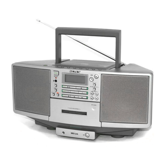
PERSONAL AUDIO SYSTEM
ZS-D5
US Model
Canadian Model
AEP Model
UK Model
E Model
KSM-213CDM/M-S
MF-D55-144
4-track 2 channel stereo
Approx. 120s (sec.) with Sony cassette C-60
TYPE1 (normal): 50 - 15,000 Hz
Full range: 8 cm (3 1/4in.) dia., 3 Ω,
cone type x 2
LINE IN jack (stereo minijack)
Minimum input level 250 mV
Headphones jack (stereo minijack)
For 16 - 68 Ω impedance headphones
LINE OUT jack (stereo minijack)
Rated output level 250 mV at load impedance
47 kΩ
OPTICAL DIGITAL OUT (CD) (optical output
connector)
Wavelength: 630 - 690 nm
4.5 W + 4.5 W (3 ohms at 10 % harmonic
distortion in DC operation)
For personal component system:
120 V AC, 60 Hz
12 V DC, 8 size D (R20) batteries
For memory back-up:
6 V DC, 4 size AA (R6) batteries
For remote commander:
3 V DC, 2 size AA (R6) batteries
AC 25 W
— Continued on next page —
Advertisement
Table of Contents

Related Manuals for Sony ZS-D5


Summary of Contents for Sony ZS-D5
- Page 1 Recording system 4-track 2 channel stereo HARMONIC DISTORTION Fast winding time Approx. 120s (sec.) with Sony cassette C-60 Frequency response TYPE1 (normal): 50 - 15,000 Hz With 3-ohm load, both channel driven from 150 - 15,000 Hz; rated 3 W per channel-...
- Page 2 AC power cord (1) CRITIQUES POUR LA SÉCURITÉ DE FONCTIONNEMENT. NE Remote commander (1) REMPLACER CES COMPOSANTS QUE PAR DES PIÈSES SONY DONT LES NUMÉROS SONT DONNÉS DANS CE MANUEL OU Design and specifications are subject to change without notice.
- Page 3 SECTION 1 SERVICING NOTE NOTES ON HANDLING THE OPTICAL PICK-UP The laser component in this product is BLOCK OR BASE UNIT capable of emitting radiation exceeding the limit for Class 1. The laser diode in the optical pick-up block may suffer electrostatic breakdown because of the potential difference generated by the charged electrostatic load, etc.
- Page 4 SECTION 2 This section is extracted from instruction manual. GENERAL LOCATION OF PARTS AND CONTROLS 1 2 3 4 5 6 7 8 @™ @¡ @º !ª !º !• !¡ !¶ !™ !§ !∞ !¢ !£ !™ TUNE/TIME SET button 1 MEGA BASS button !£...
- Page 5 — 5 —...
- Page 6 — 6 —...
- Page 7 — 7 —...
- Page 8 — 8 —...
- Page 9 — 9 —...
- Page 10 — 10 —...
- Page 11 — 11 —...
- Page 12 SECTION 3 DISASSEMBLY ZS-D5 FRONT CABINET ASSY CONTROL BOARD, LAMP BOARD, H/P BOARD MECHANISM DECK ASSY CD BLOCK ASSY, HANDLE MAIN BOARD, TUNER BOARD, POWER BOARD, REAR CABINET OPTICAL PICK UP Note : Follow the disassembly procedure in the numerical order given.
- Page 13 3-2. MECHANISM ASSY Rear cabinet assy 9 Screws (+BVTP 3 × 10) !£ MD chassis !º TC board 2 Connector (CN301) 8 Connector (CN402) !™ MF-D55-144 9 Screws (+BVTP 3 × 10) !¡ Screws (+BVTP 3 × 10) 5 Connector (CN401) 4 Connector (CN442) 3 Connector (CN441) 1 Screw...
- Page 14 3-3. CONTROL BOARD, LAMP BOARD, H/P BOARD Rear cabinet assy 0 H/P board 8 Connector (CN305) 9 Screw (+BVTP 3 × 10) 7 LANB board 5 Screws (+BVTP 2.6 × 10) 6 Connector (CN804) 2 Connector (CN802) 4 CONTROL board 3 Screws (+BVTP 2.6 ×...
- Page 15 3-5. MAIN BOARD, OPTICAL PICK UP 4 Screws (+BVTP 3 × 10) 4 Screws (+BVTP 3 × 10) 5 MAIN board 1 Connector (CN701) 2 Connector (CNP703) Optical pick up CD chassis KSM-213CDM 3 Connector (POSH SWITCH) 3-6. TUNER BOARD, POWER BOARD, REAR CABINET 7 Connector (CN904) 0 Rear cabinet 3 Screws (+BVTP 3 ×...
-
Page 16: Mechanical Adjustment
SECTION 4 SECTION 5 TEST MODE MECHANICAL ADJUSTMENT 1. HOW TO ENTER THE TEST MODE PRECAUTION Clean the following parts with a denatured-alchool-moistened Turn on the main power. While the machine is in the CD STOP swab: state, short-circuit JW824 and JW825 on the SWITCH board once. record/playback head pinch roller (Turn off the main power to exit the test mode.) - Page 17 ZS-D5 SECTION 6 ELECTRICAL ADJUSTMENT Tape Speed Adjustment PRECAUTION 2. Turn the adjustment screw and check output peaks. If the peaks AEP/Italian/UK/E model Adjustment Location: TUNER board (Side A) TUNER SECTION 0 dB = 1µV 1. Perform adjustments in the test mode.
- Page 18 ZS-D5 SECTION 7 7-2. BLOCK DIAGRAM — TUNER/CD SECTION — DIAGRAMS 7-1. CIRCUIT BOARD LOCATION AU7.5V ANT1 FM/AM FRONT-END TELESCOPIC ANTENNA QUAD VCC1 VCC2 CD MOTOR board Q23(AEP,IT,UK,E) Q18(US,CND) FM RF I MIX OUT RF IF FM IF B.P.F L-CH...
- Page 19 ZS-D5 7-3. BLOCK DIAGRAM — TC SECTION — LINE AMP IC305 J442 R-CH LINE OUT • SIGNAL PATH J441 R-CH Q107 LINE IN Q105 Q103 MUTE PB/REC Q320,329 Q326,327 Q106 FUNCTION D441 MUTE IC401 SOUND/VOLUME MUTE MUTE IC302 S441 CONTROL...
- Page 32 7-17. IC PIN FUNCTION DESCRIPTION • IC801 CXP83124A-021Q Pin No. Pin Name Description C-SCOR CD DSP command date output REG-CHK Remote control input signal C-XRST CD-system reset C-XLAT CD DSP for command latch C-DATA CD DSP command date output B-MUTE CD and TUNER mute output C-CLK CD DSP for command CLK output...
- Page 33 Pin No. Pin Name Description COM1 LCD common output COM2 LCD common output COM3 LCD common output 54 to 80 SEG0 to SEG26 LCD common output – Not used (open) – Not used (open) Record bias power source supply B/L-CONT B/L-CONTROL LINE LIFE FUNCTION output...
-
Page 34: Block Diagrams
7-18. BLOCK DIAGRAMS IC703 BA6898S LEVEL LEVEL SHIFT SHIFT OP-AMP – – DRIVER-MUTE REGULATOR BIAS – T.S.D. MONITOR – LEVEL LEVEL SHIFT SHIFT – IC302 BH3854AS — 60 —... - Page 35 IC3 BU2615S IC1 TA2008AN FM MPX BUFF BUFF BUFF BUFF AM/FM ST/MONO 1/801V LEVEL MUTE — 61 —...
- Page 36 IC702 CDX2529Q 65 66 67 Clock FSTT Error Generator Corrector RMUT demodurator Interface Serial-In LMUT ASYI Interface XTAI ASYO Asymmetry XTAO Timing Corrector ASYE Logic CKOUT BIAS Over Sampling Digital Filter XPCK Digital 3rd-Order FILO Digital Sub Code Noise Shaper FILI Processor CLTV...
- Page 37 IC701 CXA1992BR – RF SUMMING AMP PD2 IV PD1 IV – FE_BIAS SENS2 – – SENS1 LASER POWER CONTROL F IV AMP FE AMP – C OUT E IV AMP XRST DFCT – LEVEL 9 – DATA FO BIAS WINDOW COMP MIRR –...
-
Page 38: Exploded Views
Ver 1.2 1999.10 SECTION 8 EXPLODED VIEWS NOTE: • -XX, -X mean standardized parts, so they may When indicating parts by reference number, have some differences from the original one. • The mechanical parts with no reference number please include the board name. •... -
Page 39: Rear Cabinet Section
8-2. REAR CABINET SECTION J301 F901 T901 not supplied MF-D55-144 Ref. No. Part No. Description Remarks Ref. No. Part No. Description Remarks * 51 1-666-855-11 TERMINAL BOARD (US,CND) * 63 1-667-132-21 LAMP BOARD (AEP,IT,UK,E) * 51 1-666-855-21 TERMINAL BOARD (AEP,IT,UK,E) 3-017-440-01 BRACKET (L), HANDLE * 52 A-3321-150-A POWER BOARD, COMPLETE (US,CND) - Page 40 8-3. CD MECHANISM SECTION (KSM-213CDM/M-S) not supplied KSM-213 Ref. No. Part No. Description Remarks Ref. No. Part No. Description Remarks * 100 A-3293-850-A MAIN BOARD, COMPLETE (US,CND) 3-351-377-11 GEAR, DAMPER * 100 A-3293-877-A MAIN BOARD, COMPLETE (AEP,IT,UK,E) 3-931-379-21 RUBBER, VIBRATION PROOF 3-938-884-01 SPRING, CD COIL 3-931-379-31 RUBBER, VIBRATION PROOF 3-017-878-01 SLIDER, PUSH...
- Page 41 8-4. OPTICAL PICK UP SECTION not supplied M702 Ref. No. Part No. Description Remarks Ref. No. Part No. Description Remarks ! 151 8-848-483-05 OPTICAL, PIC-UP KSS-213C/Q-RP X-2626-202-1 CHASSIS ASSY (MB) (RP), MOTOR 2-627-003-02 GEAR (B) (RP) 2-626-907-01 GEAR (A) 2-626-908-01 SHAFT, SLED M702 X-2625-769-1 GEAR ASSY (MB), MOTOR The components identified by...
- Page 42 8-5. CASSETTE MECHANISM DECK SECTION-1 (MF-D55-144) HRPE101 Ref. No. Part No. Description Remarks Ref. No. Part No. Description Remarks 3-938-905-01 HEAD, LEVER * 215 3-938-916-01 BRAKE, ARM 3-938-940-01 SPRING (L) * 216 3-938-914-01 FRAME (C) 3-938-941-01 SCREW (A) * 217 3-938-913-01 FRAME (B) 3-938-906-01 AZIMUTH, SPRING * 218...
- Page 43 8-6. CASSETTE MECHANISM DECK SECTION-2 (MF-D55-144) M691 PM691 supplied Ref. No. Part No. Description Remarks Ref. No. Part No. Description Remarks 3-938-949-01 WASHER (B) 3-017-431-01 BRACKET (MM) 3-938-951-01 WASHER (D) 3-017-430-01 BELT 3-938-936-01 SPRING (H) 3-017-596-01 FLYWHEEL (R) ASSY 3-938-930-01 SPRING (B) 3-017-434-01 SCREW (H) 3-938-910-01 REEL, CAP 3-017-595-01 FLYWHEEL (L) ASSY...
-
Page 44: Electrical Parts List
BATTERY (L) BATTERY (S) SECTION 9 ELECTRICAL PARTS LIST CONTROL CD MOTOR NOTE: • Due to standardization, replacements in the • RESISTORS When indicating parts by reference number, parts list may be different from the parts All resistors are in ohms. please include the board name. - Page 45 CONTROL Ref. No. Part No. Description Remarks Ref. No. Part No. Description Remarks < IC > R837 1-249-417-11 CARBON 1/4W F R838 1-249-417-11 CARBON 1/4W F IC801 8-752-890-50 IC CXP83124A-021Q (US,CND) R839 1-249-417-11 CARBON 1/4W F IC801 8-752-894-98 IC CXP83124A-027Q (AEP,IT,UK,E) R840 1-249-417-11 CARBON 1/4W F...
- Page 46 LAMP MAIN Ref. No. Part No. Description Remarks Ref. No. Part No. Description Remarks < JACK > C215 1-161-055-00 CERAMIC 0.022uF C218 1-126-927-11 ELECT 2200uF J301 1-566-891-11 JACK (H/P JACK) C219 1-136-165-00 FILM 0.1uF C220 1-126-960-11 ELECT < COIL > C221 1-126-967-11 ELECT 47uF...
- Page 47 MAIN Ref. No. Part No. Description Remarks Ref. No. Part No. Description Remarks C713 1-136-153-00 FILM 0.01uF < DIODE > C714 1-130-493-00 MYLAR 0.068uF C715 1-126-960-11 ELECT D301 8-719-991-33 DIODE 1SS133T-77 C716 1-162-199-31 CERAMIC 10PF D302 8-719-991-33 DIODE 1SS133T-77 C717 1-126-967-11 ELECT 47uF D303...
- Page 48 MAIN Ref. No. Part No. Description Remarks Ref. No. Part No. Description Remarks Q316 8-729-037-34 TRANSISTOR KRA107M R212 1-249-427-11 CARBON 6.8K 1/4W F Q316 8-729-902-80 TRANSISTOR DTA114YS R213 1-249-419-11 CARBON 1.5K 1/4W F Q317 8-729-036-89 TRANSISTOR KTC3198GR-AT R214 1-249-417-11 CARBON 1/4W F Q318 8-729-801-84 TRANSISTOR 2SB1013-4...
- Page 49 MAIN POWER Ref. No. Part No. Description Remarks Ref. No. Part No. Description Remarks R367 1-249-441-11 CARBON 100K 1/4W A-3321-150-A POWER BOARD, COMPLETE (US,CND) R368 1-249-441-11 CARBON 100K 1/4W *********************** R369 1-249-417-11 CARBON 1/4W F A-3293-875-A POWER BOARD, COMPLETE (AEP,IT,UK,E) R370 1-249-413-11 CARBON 1/4W F...
- Page 50 POWER RETAINER SWITCH Ref. No. Part No. Description Remarks Ref. No. Part No. Description Remarks < RESISTOR > < IC > ! R901 1-211-757-11 FUSIBLE 1/2W F IC802 8-742-012-11 HY B IC SBX1976-51 ! R902 1-211-757-11 FUSIBLE 1/2W F R903 1-249-410-11 CARBON 1/4W F <...
- Page 51 Ref. No. Part No. Description Remarks Ref. No. Part No. Description Remarks A-3293-842-A TC BOARD, COMPLETE (US,CND) < DIODE > ******************* A-3293-869-A TC BOARD, COMPLETE (AEP,IT,UK,E) D401 8-719-991-33 DIODE 1SS133T-77 D402 8-719-991-33 DIODE 1SS133T-77 ******************* D403 8-719-991-33 DIODE 1SS133T-77 < CAPACITOR > <...
- Page 52 TERMINAL TUNER Ref. No. Part No. Description Remarks Ref. No. Part No. Description Remarks R606 1-249-417-11 CARBON 1/4W F 1-162-201-31 CERAMIC 12PF 1-102-821-00 CERAMIC 360PF < TRANSFORMER > 1-162-851-11 CERAMIC 0.1uF 1-102-820-00 CERAMIC 330PF T401 1-433-372-11 TRANSFORMER, BIAS OSCILLATION 1-126-964-11 ELECT 10uF ************************************************************* 1-162-306-11 CERAMIC...
- Page 53 TUNER Ref. No. Part No. Description Remarks Ref. No. Part No. Description Remarks < TRIMMER > 1-249-425-11 CARBON 4.7K 1/4W F 1-249-429-11 CARBON 1/4W 1-141-411-11 CAP, ADJ 20PF 1-249-437-11 CARBON 1/4W 1-141-411-11 CAP, ADJ 20PF 1-249-415-11 CARBON 1/4W F 1-249-412-11 CARBON 1/4W F <...
- Page 54 TUNER Ref. No. Part No. Description Remarks Ref. No. Part No. Description Remarks 1-126-933-11 ELECT 100uF < DIODE > 1-102-518-11 CERAMIC 33PF 1-162-199-31 CERAMIC 10PF 8-719-991-33 DIODE 1SS133T-77 1-162-306-11 CERAMIC 0.01uF 8-719-991-33 DIODE 1SS133T-77 1-162-306-11 CERAMIC 0.01uF 8-719-050-72 DIODE KV1370NT 8-719-050-72 DIODE KV1370NT 1-162-306-11 CERAMIC 0.01uF...
- Page 55 TUNER Ref. No. Part No. Description Remarks Ref. No. Part No. Description Remarks 1-249-425-11 CARBON 4.7K 1/4W F MISCELLANEOUS 1-247-807-31 CARBON 1/4W *************** 1-249-427-11 CARBON 6.8K 1/4W F 1-249-421-11 CARBON 2.2K 1/4W F 1-505-742-11 SPEAKER (8CM) 1-247-863-91 CARBON 1/4W 1-501-480-11 ANTENNA, TELESCOPIC 1-692-960-11 SWITCH, PUSH (1 KEY) 1-249-404-00 CARBON 1/4W F...
- Page 56 ZS-D5 Sony Corporation 98C1690-1 Printed in Japan ©1998.3 Personal A&V Products Company 9-923-270-11 Published by Quality Engineering Dept. — 82 — (Shibaura)
- Page 57 ZS-D5 Ver 1.3 2000.2 US Model Canadian Model SERVICE MANUAL AEP Model UK Model E Model 1998.11 SUPPLEMENT-1 File this supplement-1 with the Service Manual. • The following parts are changed to the new parts from the serial numbers as described below.
Need help?
Do you have a question about the ZS-D5 and is the answer not in the manual?
Questions and answers