
Subscribe to Our Youtube Channel
Related Manuals for BIRD FlightHawk


Summary of Contents for BIRD FlightHawk
- Page 1 FlightHawk RF Test Set Operation Manual ©Copyright 2020 by Bird Technologies Instruction Manual Part Number 920-7003A004-1 Rev. P1...
-
Page 2: Safety Precautions
Safety Precautions The following are general safety precautions that are not necessarily related to any specific part or procedure, and do not necessarily appear elsewhere in this publication. These precautions must be thoroughly understood and apply to all phases of operation and maintenance. WARNING Keep Away From Live Circuits Operating Personnel must at all times observe general safety precautions. -
Page 3: Safety Symbols
Safety Precautions Safety Symbols WARNING Warning notes call attention to a procedure, which if not correctly performed, could result in personal injury. CAUTION Caution notes call attention to a procedure, which if not correctly performed, could result in damage to the instrument. The caution symbol appears on the equipment indicating there is important information in the instruction manual regarding that particular area. -
Page 4: Caution Statements
FlightHawk RF Test Set Caution Statements The following safety cautions appear in the text where there is danger of damage to equipment, and are repeated here for emphasis. CAUTION Do not connect the unit to a PC USB port. File transfer must be done using a USB Drive. -
Page 5: Safety Statements
Safety Precautions Safety Statements USAGE ANY USE OF THIS INSTRUMENT IN A MANNER NOT SPECIFIED BY THE MANUFACTURER MAY IMPAIR THE INSTRUMENT’S SAFETY PROTECTION. EL USO DE ESTE INSTRUMENTO DE MANERA NO ESPECIFICADA POR EL FABRICANTE, PUEDE ANULAR LA PROTECCIÓN DE SEGURIDAD DEL INSTRUMENTO. - Page 6 FlightHawk RF Test Set SERVICE SERVICING INSTRUCTIONS ARE FOR USE BY SERVICE - TRAINED PERSONNEL ONLY. TO AVOID DANGEROUS ELECTRIC SHOCK, DO NOT PERFORM ANY SERVICING UNLESS QUALIFIED TO DO SO. SERVICIO LAS INSTRUCCIONES DE SERVICIO SON PARA USO EXCLUSIVO DEL PERSONAL DE SERVICIO CAPACITADO.
-
Page 7: About This Manual
This manual covers the operating and maintenance instructions for the following models: 7003A004-1 Test Set with FlightHawk-AV plus 5017D-AV WPS and 25 Watt Termination Changes to this Manual We have made every effort to ensure this manual is accurate at the time of publication. -
Page 8: Chapter Layout
Data Save and Export — Instructs the user on methods for saving FlightHawk-AV generated data and methods for exporting the data to external devices. RF Power Measurement — Provides instruction on the use of the Bird RF Meter App and the Wideband Power Sensor, includes instructions for utilizing the RF power measurement capabilities of the power sensor. -
Page 9: Table Of Contents
FlightHawk-AV Default Settings ........7... - Page 10 Chapter 3 Calibration ........28 Calibrating the FlightHawk-AV Analyzer ......28...
- Page 11 Save Files on FlightHawk-AV ........39...
- Page 12 Bird RF Test Set Readings Menu ..........51 Changing Readings Menu Settings .
- Page 13 Replacing the Battery ......... . . 74 FlightHawk RF Test Set Calibration ....... . 74 Storage .
- Page 14 Bird RF Test Set RF Cable (3 Meter) Specifications ....... . . 84 5017D-AV Specifications .
-
Page 15: Chapter 1 Introduction
Chapter 1 Introduction The FlightHawk RF Test Set is designed to aid aircraft maintenance technicians in quickly diagnosing and resolving problems with aircraft communications systems. Figure 1 FlightHawk RF Test Set Splash Screen The FlightHawk RF Test Set, simplifies the following tasks: 1. -
Page 16: Items Supplied
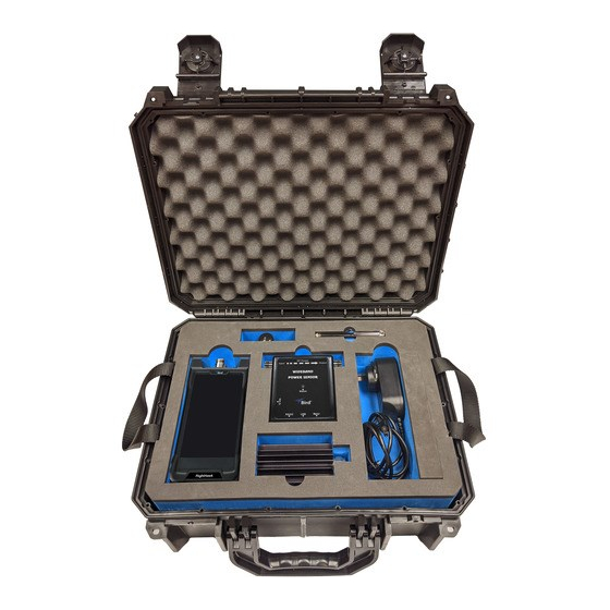
FlightHawk RF Test Set Items Supplied Figure 2 FlightHawk RF Test Set The FlightHawk RF Test Set contains the equipment in the following table. Description Part Number FlightHawk-AV Analyzer FlightHawk-AV Wideband Power Sensor, Model 5017 5017D-AV Cable, RF N(m) to N(f), 3m... -
Page 17: Flighthawk-Av Analyzer
The FlightHawk-AV is a multifunction test instrument for use in installation and maintenance of RF communications systems. The unit has a frequency range of 1 MHz to 6 GHz. Additional FlightHawk-AV specifications can be found in the specifications chapter, See "Specifications"... -
Page 18: Measurement Capability
The FlightHawk-AV includes an RF power meter application. The Bird RF Meter is an Android App which allows the FlightHawk-AV to be used with the Bird 5017D- AV RF Power Sensor available in the FlightHawk RF Test Set. To measure transmitter RF power, connect the power sensor to the FlightHawk-AV. -
Page 19: Chapter 2 Flighthawk-Av Basic Operation
Appendix B Measurement Interface The FlightHawk-AV measurement interface consists of a measurement display area, menus and control options. The user taps the screen to access menus, change settings, perform measurements and save results. See Table 1 on page 6 for explanations. - Page 20 Item Description Current Date and Time, latitude and longitude. Note: Location services must be set to On for the FlightHawk-AV to display latitude and longitude data. See "Accessing Communication Services" on page 47 Measurement Mode, press to display Measurement Mode menu.
-
Page 21: Flighthawk-Av Default Settings
FlightHawk-AV Basic Operation FlightHawk-AV Default Settings Description Default Setting Touchstone Data Format RI - Real-Imaginary Allocation of Channels Active Channel Number Marker Value Identification Capacity 8 digits (Stimulus) Marker Value Identification Capacity 5 digits (Response) Vertical Divisions Traces per Channel... -
Page 22: Setting The Measurement Frequencies
Note: Changing the frequency settings will automatically turn calibration off. Always set the frequency before calibrating the unit. Note: If a frequency that is outside of the range of the FlightHawk-AV is entered, the FlightHawk-AV will override the entry and set the minimum or maximum frequency of the model. -
Page 23: Setting The Measurement Data Points
FlightHawk-AV Basic Operation Setting the Measurement Data Points Select the number of data points to take during a measurement. There are seven data point options: 51 points 101 points 201 points 401 points 801 points ... -
Page 24: Setting The Distance Units And Cable Values (Dtf Menu)
2. Set stop distance. Windowing Windowing is an option on the FlightHawk-AV that will digitally average the data on the displayed trace, in effect, making the trace appear smoother. In some situations, it will make individual problems easier to spot, but in others it may mask details that are needed. -
Page 25: Velocity
FlightHawk-AV Basic Operation Velocity 1. Select Velocity. 2. Set speed value. Note: Manually enter cable velocity value or select the cable type from the cable list. Cable Loss 1. Select CableLoss. 2. Set cable loss values. Note: • Manually enter cable loss value or select the cable type from the cable list. -
Page 26: Trace Settings
The number of traces displayed and the minimum and maximum grid scale values can be manually changed. Note: FlightHawk-AV is capable of displaying up to 4 traces. 1. Press the Trace name (e.g. Tr1) to select the active trace. See... -
Page 27: Adjusting The Trace Within The Selected Scale
FlightHawk-AV Basic Operation Adjusting the trace within the selected scale Note: Scale settings only affect the active trace, if more than one trace is currently displayed, select the desired trace before changing scale. 1. Press SCALE icon. See Figure 7 on page 13 2. -
Page 28: Limit Line
FlightHawk RF Test Set Limit Line The limit line helps to set off those parts of a trace that are outside of the acceptance (limit) values. It appears as a red horizontal line at the limit line value. The part of the trace that is not acceptable will display in white. -
Page 29: Step
FlightHawk-AV Basic Operation Step Sets the numerical value the limit line will move when the Move UP or Move Down button are pressed. Press the field to enter a value. Move Up Press to move limit line up the vertical scale. Each press will move the limit line the value in the Step field. -
Page 30: Markers
Each marker is displayed as a triangle pointer. Up to six markers can be used with each trace to visually indicate the trace value at specific frequency points. Only markers for the active trace are displayed. The FlightHawk-AV analyzer displays the frequency and signal value for each marker at the top of the screen. The difference (delta) in frequency between two markers can also be displayed. -
Page 31: Step
FlightHawk-AV Basic Operation Step Sets the frequency value the active marker will move when the Move Left or Move Right buttons are pressed. Press the Step field to enter a value. Moves the position of the marker left or right by the step entered. -
Page 32: Using Delta Markers
FlightHawk RF Test Set Using Delta Markers The delta marker feature displays the difference (delta) in both frequency (or distance) and value between the active marker and all other markers. All markers follow the current trace only. Note: The Delta marker compares points on one trace and at least two markers must be displayed for the Delta Option to work. - Page 33 FlightHawk-AV Basic Operation 3. Press MKR icon, and select MoveDelta. Note: shows Marker 1-3 is now highlighted. Figure 14 Figure 14 Highlighted Delta Marker...
-
Page 34: Peak Search Between Markers
FlightHawk RF Test Set Peak Search Between Markers The peak search between markers feature causes a marker to find the peak between two other markers. M1 ~ M2 selection causes marker 3 to move to the peak signal between marker 1 and marker 2 positions. M4 ~ M5 selection causes marker 6 to move to the peak signal between marker 4 and marker 5 positions. -
Page 35: Utility Menus
FlightHawk-AV Basic Operation Utility Menus Pressing the Menu icon will display the utility menus: MEM, FREQ, RESET, FILE, PNG, SYS. See Figure 16 These menus are described in this section with the exception of the FREQ menu, the FREQ menu is described in "Setting the Measurement Frequencies"... -
Page 36: File Menu
FlightHawk RF Test Set FILE Menu Pressing the FILE icon will display the file menu. See Figure 17 Figure 17 File Menu Saving and Recalling Traces Traces and measurement data can be saved and recalled from either the unit’s internal memory or an external USB thumb drive. See "Data Save and Export"... - Page 37 ON screen shots will be in color. See Figure 18 Note: The default setting for Color Screen Shot option is OFF. If the reset function is executed on the FlightHawk-AV, the Color Screen Shot option is reset to OFF. Figure 18...
- Page 38 Delete User File Press to display the Delete User File dialog box. The Delete User File dialog box allows any one file type or all file types to be deleted from the FlightHawk-AV. Figure 19 For procedure to delete files see "Data Save and Export"...
-
Page 39: Reset Icon
Figure 22 Save Multiple Files RESET Icon The reset menu will reset the FlightHawk-AV to default settings. All current data is cleared including calibration, and all menus are reset to default. Saved data is not affected by a reset. 1. Press the Menu icon. -
Page 40: Sys Menu
Note: GPS coordinates, when selected, will appear on the display along with the date and time, see "Measurement Interface" on page Note: Location services must be set to On for the FlightHawk-AV to latitude and longitude data. See display "Accessing Communication... -
Page 41: Exit
Figure 25 System Settings EXIT Press the exit icon on the SYS menu to close the FlightHawk-AV application. About Screen Press the information icon on the SYS menu opens the About Screen. The About screen displays the software version and the device serial number. -
Page 42: Chapter 3 Calibration
Chapter 3 Calibration Calibrating the FlightHawk-AV Analyzer For best results, set the frequency and calibrate the Bird Site Analyzer immediately before taking measurements. Note: Use a precision open, short, load (OSL) calibration standard or “Calibration Combo” for accurate measurement results. -
Page 43: Chapter 4 Measure Match Mode
Example - For a 450 MHz antenna, set the start frequency at 400 and the stop frequency at 500 MHz, for an 800 MHz antenna, set the start frequency at 700 and the stop frequency at 1,100 MHz. 5. Calibrate the FlightHawk-AV. See "Calibration" on page 28... -
Page 44: Interpreting The Measurement
Damage to the units RF module will result. Note: Antenna systems can build up a static charge large enough to damage the FlightHawk-AV, if discharged through the device. It is recommended a load or attenuator be used to bleed off any static charge prior to connecting the FlightHawk-AV to the system. -
Page 45: Cable Loss Measurement
500 MHz. For an 800 MHz antenna, set the start frequency at 700 and the stop frequency at 1,100 MHz. 4. Connect a phase stable cable to the FlightHawk-AV Analyzer antenna test port. 5. Calibrate the FlightHawk-AV Analyzer. -
Page 46: Interpreting A Cable Loss Measurement
FlightHawk RF Test Set 11. Place a marker (mark 2) at the maximum loss point within the frequency band on the trace. 12. Save and label the trace, if appropriate. "Recall Trace Data" on page 41 Interpreting a Cable Loss Measurement The graph below shows a typical cable loss measurement. -
Page 47: Chapter 5 Fault Location Mode
Fault location identifies the position of impedance discontinuities (reflections) within the antenna system. The measurement results are displayed on an x-y graph. Distance from the FlightHawk-AV Analyzer is shown on the x-axis, while relative magnitude of the discontinuity is shown on the y-axis. -
Page 48: Data Points
Consult the cable manufacturer's specifications to get the velocity of propagation value for the cable being used. The FlightHawk RF Test Set includes a pre-installed cable list that includes parameters for majority of RF cables used in the aircraft industry. -
Page 49: Selecting Fault Location Mode
Press cable list, select the cable type from the list, cable values will be automatically entered for testing. Note: The default cable list included on all FlightHawk-AV Aviation kits is called “Aviation_Cablelist” that has majority of data for cables used in... - Page 50 FlightHawk-AV to the system. 12. Connect the FlightHawk-AV Analyzer to the cable being tested. Note: If the FlightHawk-AV Analyzer is calibrated with a phase stable cable connected to its antenna port, do not remove the cable. Connect it to the cable to be tested.
-
Page 51: Interpreting The Fault Location Measurement
A large spike (fault) near the FlightHawk-AV will mask other faults farther away. When a large spike near the FlightHawk-AV is found, fix it and then repeat the Fault Location measurement. -
Page 52: Chapter 6 Data Save And Export
File transfer must be done using a USB Drive. Trace Data in CSV File Format FlightHawk-AV can track data of a single trace and then save the data as a comma delimited values (CSV) file. The CSV file contains a list of data separated by commas. -
Page 53: Save Files On Flighthawk-Av
Z0——reference impedance F[n]——Frequency about point N {…}’—— {(RI) |(MA) |(DB)} {…}”——{(RI) |(MA) |(DB)} Save Files on FlightHawk-AV The FlightHawk-AV Analyzer automatically names files using a time-date format, this can be changed during the save operation. Figure 34 FlightHawk-AV File Names DATE... - Page 54 FlightHawk RF Test Set Figure 35 File Menu 3. Select the format of the saved file: Data can be saved as cst or sta trace data. Data can be saved as a S1p file. Data can be saved as a datafile (.csv).
-
Page 55: Recall Trace Data
Data Save and Export Figure 36 File Save Dialog Recall Trace Data Data in sta or cst data files can be recalled and displayed with the current data trace. 1. Press the Menu icon. 2. Press the FILE icon to display the file menu. See Figure 35 3. -
Page 56: Deleting Flighthawk-Av Stored Data Files
Recall Sta Data and Running Data 7. Press OFF to remove the recalled trace data. Deleting FlightHawk-AV Stored Data Files This procedure can be used to delete any data files stored by the SiteHawk App. 1. Press the Menu icon. -
Page 57: Data Transfer Function
Press the check box next to each file type to select those files for deletion. 6. Press DELETE. Data Transfer Function Data transfer from the FlightHawk-AV may be accomplished using a USB Drive or via Bluetooth transfer. For instructions on how to make transfers see "Data Transfer via USB Drive" on page 43 "Data Transfer via Bluetooth"... - Page 58 FlightHawk RF Test Set 4. Select LOCAL. See Figure 40 5. Select Internal Storage. 6. Navigate to the location of the file. Figure 40 File Selection 7. Press to select the file to be copied. See Figure 41 8. Press the Copy icon.
-
Page 59: Ejecting Usb Drive From Settings Menu
Data Save and Export Figure 42 Paste Files 13. Exit the File Manager. 14. Pull down the notification area at the top of the display screen. See Figure 43 Figure 43 Eject USB Storage 15. Tap EJECT. Ejecting USB Drive from Settings Menu 1. -
Page 60: Data Transfer Via Bluetooth
4. Wait for Ejected to be displayed under the USB name. 5. You may now remove the USB Drive. Data Transfer via Bluetooth Files may be transfered to/from the FlightHawk-AV using the following steps. 1. Press Home key on the FlightHawk-AV display. 2. Select Settings. -
Page 61: Flighthawk-Av Communications Settings
Data Save and Export FlightHawk-AV Communications Settings The FlightHawk-AV utilizes WiFi, Bluetooth, and GPS to perform the various functions described in the previous sections. These communications functions may be turned on and off using the pull-down notification area at the top of the FlightHawk-AV’s display area, See... -
Page 62: Chapter 7 Rf Power Measurement
3. Connect USB OTG Cable to FlightHawk-AV. Note: Bird RF Meter App will automatically launch. 4. Check the box to select Bird RF Meter as the default app. This setting allows the Bird RF Meter App to automatically connect to this sensor in the future. -
Page 63: Wideband Rf Power Sensor (Wps) Measurements
RF Power Measurement 8. Connect RF line so that the arrow on the sensor points towards the load. Figure 48 RF Power Measurement Setup Note: Risk of unintentional signal transmission, broadcast or interference! Always disconnect transmit and/or receive antenna. Refer to your official maintenance manual or diagnostic procedure for exact test instructions. -
Page 64: Measurement Procedure
FlightHawk RF Test Set Measurement procedure 1. Connect the 5017D-AV sensor to the cable or communications system. See "Sensor Connection" on page 48 2. Zero the WPS. See "Zeroing a Sensor" on page 50 3. Tap the Display Controls Menu 4. -
Page 65: Sensor Displays And Menus
RF Power Measurement Sensor Displays and Menus Figure 49 Power Meter Display Item Used to configure the sensor and choose the format Display Controls for displaying measurement data. See "Display Menu Controls Menu" on page 53 Displays the numerical readings available/selected Display Area/ device readings. -
Page 66: Changing Readings Menu Settings
"Arranging the Readings Menu Order" on page 52 Changing Readings Menu Settings Note: The Bird RF Meter will save all settings for each sensor (by serial number). Sensor specific settings will automatically load when the sensor is connected. All settings are saved in Session Files. -
Page 67: Display Controls Menu
RF Power Measurement Display Controls Menu Figure 51 Display Controls Menu Sensor Configuration Menu Measurement Type — Choose the Measurement Type by tapping one of the available radio buttons in the menu. Offset — Offset menu is used to enter the total value of all couplers and attenuators connected to the sensor (for example, the coupling factor of a directional coupler). -
Page 68: How To Display The Reading Table
FlightHawk RF Test Set How to Display the Reading Table 1. Tap the Display Controls Menu to display the graph options. 2. Tap Reading Table. Graph Types Any power measurement on the readings menu may be displayed on a graph. -
Page 69: How To Display A Graph
RF Power Measurement How to Display a Graph 1. Tap the Display Controls Menu to display the graph options. 2. Tap the name of graph type you wish to display (Time, Bar, Data). Note: It is recommended a descriptive name be used as graph names, including graph type and other distinguishing information, since multiple graphs may be saved. -
Page 70: Bar Graph Controls
FlightHawk RF Test Set Bar Graph Controls Note: Graph controls are located in the Sensor Operation Menu . Pause/Resume When pause is tapped, graph data collection is stopped and the bar is paused. When resume is tapped, data collection begins and bar begins moving. -
Page 71: Data Graph Controls
RF Power Measurement Data Graph Controls Note: Graph controls are located in the Sensor Operation Menu . Pinch the graph to zoom in or zoom out. Swipe up, down, left, or right to move the trace within the graph area. ... -
Page 72: Marker List
FlightHawk RF Test Set Marker List 1. Tap the Sensor Operation Menu . 2. Tap Marker List. When Marker List is tapped, marker list is displayed on the screen to the right or below the chart. The marker list is removed from the screen by tapping Marker List a second time. -
Page 73: Time Graph Controls
RF Power Measurement Time Graph Controls Any measurement can be displayed in graphical or tabular format. See "How to Display a Graph" on page 55 Note: Graph controls are located in the Sensor Operation Menu . Touching the graph area will stop the trace on the screen, however data will continue to be collected. -
Page 74: Graph Scale
FlightHawk RF Test Set Graph Scale The graph scale on the Y-axis may be changed by manually entering the minimum and maximum scale values. 1. Tap the Sensor Operation Menu . 2. Tap Graph Scale to display the dialog. 3. Tap drop-down list. Select Custom. -
Page 75: Sensor Operations Menu
RF Power Measurement Sensor Operations Menu Figure 55 Sensor Operation Menu Pause/Resume — The Pause option will stop the updates of measurement readings and graphs. Load Preset — This option allows you to load a preset configuration file, see Session Files for details. Device Actions —... -
Page 76: Device Actions
"Zeroing a Sensor" on page 50 Logging Sensor data can be logged by the Bird RF Meter App. Logging saves all the sensors active readings into a text file. Logging can be started on the Sensor Operations Menu . Logs are saved using the following file naming convention:... -
Page 77: Log File Definition
RF Power Measurement Log File Definition Section 1: Data Definition, often referred to as an Object. The data logged will vary according to the sensor connected when the log file is created. Section 1 includes: Model, serial number, date and time log was created ... -
Page 78: Importing Logs Into Excel
FlightHawk RF Test Set Importing Logs into Excel This procedure will display each group of results on one row with each measurement and values grouped by columns. 1. Transfer the log files to a PC. 2. Open an Excel spreadsheet. -
Page 79: Preferences Menu
Bird RF Meter Preferences Menu Network Scan — This menu option scans the WiFi network the android device is connected to for any Bird devices connected to the same network. Add Connection — The menu is used to manually connect to a Bird Device on the WiFi network the android device is connected to. -
Page 80: Session Files
FlightHawk RF Test Set Session Files Session List Definitions Session files are used to initialize the Bird RF Meter App when a Bird Power Sensor is connected. The following definitions describe the different session files. Figure 59 Session List When a power sensor is connected to the Bird RF Meter the first time the Generic Session File (Default Preset if created) is used to initialize the App then a Serial Number Specific Session File is automatically created. -
Page 81: Open The Session List
Note: You must delete any previous session files so your Default Preset will be used as the default Session File. This allows the same custom setup to be viewed every time you connect to the same type of Bird Power Sensor. -
Page 82: Export Session File
FlightHawk RF Test Set Export Session File When you connect to a Bird Power Sensor with the Bird RF Meter App a Serial Number Specific Session File is created. You can also save your settings as the default settings for your power sensor type in a Default Preset or Preset. All of these file types can be exported from the Bird RF Meter App for use on other Android devices. -
Page 83: Delete Session File
RF Power Measurement Delete Session File 1. Open the Session List. 2. Press the Session File you wish to delete until the until the delete menu is displayed. 3. Tap Delete. Measurement Descriptions Average Power Average power is a measure of the equivalent “heating” power of a signal, as measured with a calorimeter. -
Page 84: Vswr
VSWR VSWR measures the relation between forward and reflected average power. The Bird Wideband Power Sensor calculates the VSWR from the Forward and Reflected Average Power measurements. Rho and Return Loss are also the same measurement, but in different units: Rho ... -
Page 85: Video Filter
RF Power Measurement Video Filter Figure 61 Video Filter Settings, 300 kHz Signal Filter Correct Filter Too Small Filter Too Wide Noise Signal Except for average power and VSWR measurements, all WPS measurements rely on a variable video filter to improve accuracy. This filter can be set to either 4.5 kHz, 400 kHz, or full bandwidth (10000kHz). -
Page 86: Burst Average Power
FlightHawk RF Test Set Burst Average Power Figure 62 Burst Average Power Peak Envelope Power 100 W Burst Average Power 50 W Average Power Burst Width Period Burst width (BW) is the duration of a pulse. Period (P) is the time from the start of one pulse to the start of the next pulse. -
Page 87: Chapter 8 Maintenance
Chapter 8 Maintenance Cleaning Clean the FlightHawk-AV Analyzer only with a soft cloth dampened with mild detergent and water. Do not use any other type of cleaning solution. CAUTION Do not touch the center pin of the Antenna Test Port with bare hands, water, or emery cloth. -
Page 88: Replacing The Battery
The internal battery pack 1. Remove two screws and remove battery access cover. Figure 63 Battery Access 2. Carefully disconnect battery cable from connector on FlightHawk-AV. Figure 64 Battery Removal 3. Connect new battery cable to connector in the battery compartment. -
Page 89: Storage
Maintenance Storage Store the FlightHawk-AV Analyzer in an enclosed case and in an environment that does not exceed values listed in the Specifications section. Ensure that the equipment is stored away from dust, acidic and alkaline environment, explosive gas, and other causes of corrosion. -
Page 90: Delete Cable From Cable List
FlightHawk RF Test Set Figure 66 Enter Cable Data 6. After cable information is entered press OK. Delete Cable from Cable List Note: Only cables added by the user may be deleted using this method. 1. Press DTF icon. 2. Press CableList option to display the Cable List. See Figure 65 3. -
Page 91: Recall Cable List
Maintenance Recall Cable List Note: This procedure is used to load a Cable List different from the Cable List currently displayed. 1. Press DTF icon. 2. Press CableList option to display the Cable List. See Figure 65 3. Press the Recall button. See Figure 68 Figure 68 Recall Cable List Dialog Box... -
Page 92: Edit Cable List On A Pc
FlightHawk RF Test Set Edit Cable List on a PC 1. Download the Cable List Editor from FlightHawk-AV page on the Bird Website, and save on a PC. 2. Copy the file CableList.ini from the SiteHawk folder on the FlightHawk-AV. - Page 93 12. Copy the updated Cable List to a USB drive. 13. Exit the SiteHawk App on the FlightHawk-AV Analyzer. 14. Copy the updated CableList.ini file to the FlightHawk-AV and save in the original Cable List folder. "Data Transfer Function " on page 43 15.
-
Page 94: Firmware Update
3. Click on SiteHawk App VX.XX to download. 4. Connect the USB drive to the PC. CAUTION Do not connect the FlightHawk-AV to a PC USB port. File transfer must be done using a USB Drive. 5. Transfer the SiteHawk_XXX.apk update file to the USB drive. -
Page 95: Customer Service
If the unit needs to be returned for any reason, request an Return Material Authorization (RMA) through the Bird Technologies website. All instruments returned must be shipped prepaid and to the attention of the RMA number. -
Page 96: Chapter 9 Specifications
Specifications FlightHawk RF Test Set Calibration The FlightHawk RF Test Set includes a certificate of calibration at the time of manufacture, the calibration should be renewed at two year intervals to ensure accuracy is maintained as indicated in the following specification tables. - Page 97 Power Measurement Yes, with RF Meter App Visit www.birdrf.com for a list of sensors Compatible Devices compatible with the Bird RF Meter App. Storage Capacity 16 GB Immunity to Interfering Signals +13 dBm CE compliant. EMC, Safety, and RoHS 10 hours continuous use Battery 7.4 V, 6800 mAh...
-
Page 98: Calibration Combo Specifications
FlightHawk RF Test Set Calibration Combo Specifications Frequency DC - 6.0 GHz Resistance 50 Ohm Average Power ≤ 1 W Connectors Load Return Loss ≤ –35 dB ≤ 1.032 VSWR Open ≤ ± 0.6° Phase Deviation Short Phase Deviation ≤ ± 0.6°... -
Page 99: 5017D-Av Specifications
DC Connector 7 – 18 Vdc, < 100 mA Data Logging In VPM/Bird Power Meter software 1 Derate maximum average power rating from 500W at 300MHz to 100W at 1GHz using a straight line on a log-log scale. Average RF Power 500 mW –... -
Page 100: Match Measurement
FlightHawk RF Test Set Match Measurement Measurement Range: Return Loss 0 to 23 dB Rho ( 0.07 to 1.0 1.15 to 99.9 VSWR Forward Power, Min 0.05 W Measurement Uncert. Figure 74 on page Figure 74 Match Measure Uncertainty... -
Page 101: Peak Envelope Rf Power
Specifications Peak Envelope RF Power RF Power Range 13.3 – 1300 W Measurement Uncert.: ± (7% of reading + 0.7 W) burst width > 200 µs 1 µs < b.w. < 200 µs ± (10% of reading + 1.4 W) burst width <... -
Page 102: Physical And Environmental Specifications
FlightHawk RF Test Set Physical and Environmental Specifications Temp, Operating –10 to +50 °C (+14 to +122 °F) Temp, Storage –40 to +80 °C (–40 to +176 °F) Mechanical Shock and MIL-PRF-28800F class 3 Vibration Humidity, Max 95% (non-condensing) Altitude, Max 15,000 ft. - Page 103 Specifications...
-
Page 104: Limited Warranty
Limited Warranty The FlightHawk RF Test Set is warranted to be free from defects in material and workmanship for a period of three (3) years, unless otherwise specified, from date of shipment and to conform to applicable specifications, drawings, blueprints and/or samples. Seller’s sole obligation under these warranties shall be to issue credit, repair or replace any item or part thereof which is proved to be other than as warranted;... -
Page 105: Appendix A Technical Tip
Appendix A Technical Tip TECHNICAL TIP (FOR INFORMATION ONLY) Coaxial Cable & Antenna System Inspection with a Frequency Domain Reflectometer INTRODUCTION: This Technical Tip and user instruction manual establishes the standards of operation for the personnel unfamiliar with this unit to understand it, identify its parts, and operate it in accordance with proper procedures, operating techniques, precautions and limitations. - Page 106 FlightHawk RF Test Set but may also harm the transmitter if the reflection is excessive. The recommended FDR is an easy to use handheld tester, with a Go/No-Go function by use of a limit line and simple distance to fault measurement.
- Page 107 4) DISTANCE TO FAULT: Displays distance in ft/in or M/cm to the VSWR or Return Loss (RL) fault without disconnecting. PREPARATION The FlightHawk RF Test Set has been designed with a user friendly GUI “Graphical User Interface” which provides an intuitive understanding of the man/machine interaction thereby greatly simplifying the learning experience.
- Page 108 (c) Recall previously saved set-up OR select “Measure Match Mode” to manually input settings. 1) FlightHawk-AV status, calibration result, and tracing data can be saved to the instrument, and can be recalled to be displayed on the sweep display area. The parameters for this instrument setting include the scale, trace, cursor and analysis.
- Page 109 Technical Tip 2) Select MEASURE MATCH MODE a) Push trace measurement field to display menu. b) Select SWR or Return Loss from the Measurement Mode menu. c) Select the number of Data Measurement points (default to 801). d) Set the Frequency range: NOTE: Changing the frequency settings will automatically turn the calibration off.
- Page 110 FlightHawk RF Test Set 3) CALIBRATE: For best results, you can set the frequency and calibrate the Bird Site Analyzer immediately before taking measurements. NOTE: Use a precision open, short, load (OSL) calibration standard or “Calibration Combo" for accurate measurement results.
- Page 111 NOTE: During calibration, the color of the icon display is yellow. NOTE: Whenever the FlightHawk-AV has been calibrated, a COR ON indicator is shown in the lower right corner of the display. Anytime the frequency is changed, the calibration is turned OFF and the COR ON disappears, requiring the unit to be re-calibrated.
- Page 112 FlightHawk RF Test Set sweep display area to indicate if the active signal is within or outside the limits set by the limit line. Table 1. TYPICAL RF SYSTEM FREQUENCY RANGE CHART Maximum Voltage Cable and System Operating Standing Wave...
- Page 113 OTHER CONDUCTORS. IF YOU TOUCH THESE CONDUCTORS, ELECTROSTATIC DISCHARGE CAN CAUSE DAMAGE TO THE COMPONENTS. (c) Connect the FlightHawk-AV to the device for the test. 1) Connect the test cable or phase stable cable (including the bench plug adapter) to the FDR’s N-type connector.
- Page 114 FlightHawk RF Test Set a) If the system passes, put the airplane back to its usual condition. b) If the system fails, isolate by using the distance to fault feature using steps below, Fault Isolation of Coaxial Cable and Antenna System.
- Page 115 Technical Tip value that is a few feet or meters greater than the entire length of the cable system. (f) Select Units to m (meters) or ft (feet). (g) Enter Cable data using one of the following methods: NOTE: Manually enter cable velocity value and Cable Loss Value or select the cable type from the cable list.
- Page 116 2) Select Fail Flag (On/Off). Push to toggle the fail flag Off. (i) Calibrate the FlightHawk-AV. See “Calibration” above. (j) Connect the FlightHawk-AV Analyzer to the cable and antenna system being tested. (k) Wait for a minimum of 10 seconds for the sweep to complete the update.
- Page 117 Technical Tip (c) Spikes where there are no components represent faults. Record the distance and then examine the line at that point for damage. (d) The largest spike is usually due to the antenna. Typically the trace after the antenna can be ignored (Ghosting).
- Page 118 FlightHawk RF Test Set The graph below (Figure 1) shows a typical Fault Location measurement for an antenna system. Figure 1 Typical Fault Location Measurement The table below (Table 3) shows typical component return loss. Table 3. Typical Component Return Loss...
- Page 119 Technical Tip Figure 2 Good Test C. PUT THE AIRPLANE BACK TO ITS USUAL CONDITION (1) Disconnect the TDR adapter cable from the EE Rack Bench Plug. (2) Remove the 50 ohm terminator from the other end of the applicable cable if used for troubleshooting. (3) To install the applicable black box, do this task: E/E Box Installation.
- Page 120 A-16...
-
Page 121: Appendix B Automated Operation
FlightHawk-AV and test specific communications and navigation systems. Modes of Operation The FlightHawk-AV is available with two modes of operation: Automatic Mode — Automatic Mode consists of predefined tests, tailored to the specific systems available on a given aircraft. These tests are designed to be used in conjunction with troubleshooting procedures in the aircraft’s technical... - Page 122 Mode is non-standard software. When Automatic Mode is installed a Mode Selection Screen ( ) is Figure 3 displayed, when the FlightHawk-AV is powered on, allowing the user to select which mode they wish to use. Figure 3 Mode Selection Screen...
- Page 123 Automated Operation When the technician selects Automatic Mode, they are presented with an aircraft selection screen. See Figure 4 Note: These tests are designed to be used in conjunction with trouble- shooting procedures in the aircraft’s technical manual The technician will choose the appropriate aircraft by tapping the screen. Figure 4 Aircraft Selection Screen...
- Page 124 FlightHawk RF Test Set The FlightHawk-AV contains predefined configurations for testing an aircraft’s communications or navigation systems. Each system on the aircraft will be listed, the technician chooses the appropriate system by tapping the screen. Figure 5 Note: If the aircraft contains more systems than will fit on the screen, scroll down on the screen to see the additional systems.
- Page 125 Automated Operation The Aircraft’s troubleshooting procedures will specify where to connect the FlightHawk-AV for each system. Once the FlightHawk-AV is connected to the system’s cabling, tap the test button. See . The FlightHawk-AV automatically "VSWR Test Screen" on page B-5 configures the parameters required to test the VSWR of the selected system, then the test is run.
- Page 126 Detailed Results - tapping the Detailed Results button will open the FlightHawk-AV’s measurement display. The trace created during the test will appear in the display and the technician will be able to see the exact values returned during the test. See Figure 8 on page B-7 ...
- Page 127 Automated Operation The Detailed Test results are displayed on the FlightHawk-AV’s measurement display. See Figure 8 When a VSWR test fails, the technician can view the trace and see exactly how far the VSWR is above the test’s threshold. To return to the previous Test Results Screen, tap (back button).
- Page 128 FlightHawk RF Test Set When New Test is selected on a test results screen ( ) the Figure 7 on page B-6 technician is presented with the New Test Selection Screen, see Figure 9 This screen gives the technician the option of selecting a new aircraft for testing, or selecting a different communications system on the same aircraft.
- Page 129 Automated Operation Advanced Mode Advanced Mode consists of manually configuring the FlightHawk-AV parameters to perform measurements. Prior to using the FlightHawk-AV in advanced mode you should familiarize yourself with the basic operation of the unit. covers the basic Chapter 2...
Need help?
Do you have a question about the FlightHawk and is the answer not in the manual?
Questions and answers