
Related Manuals for BIRD AT-800


Summary of Contents for BIRD AT-800
- Page 1 AT-800 Antenna Tester Operation Manual © Copyright 2016 by Bird Technologies, Inc. Instruction Book Part Number 920-AT800 Rev N...
-
Page 2: Safety Precautions
Safety Precautions The following are general safety precautions that are not necessarily related to any specific part or procedure, and do not necessarily appear elsewhere in this publication. These precautions must be thoroughly understood and apply to all phases of operation and maintenance. WARNING Keep Away From Live Circuits Operating Personnel must at all times observe general... -
Page 3: Safety Symbols
Safety Precautions Safety Symbols WARNING Warning notes call attention to a procedure, which if not correctly performed, could result in personal injury. CAUTION Caution notes call attention to a procedure, which if not correctly performed, could result in damage to the instrument. -
Page 4: Warning Statements
AT-800 Antenna Tester Warning Statements The following safety warnings appear in the text where there is danger to operating and maintenance personnel, and are repeated here for emphasis. WARNING Care should be taken when handling batteries. Do not heat or dispose of batteries in fire. May burst or release toxic materials. -
Page 5: Caution Statements
CAUTION 250mW max. input Exceeding the maximum input will cause damage to internal components. Do not connect transmitter output to the AT-800. Damage can also be caused by testing antennas near other transmitting antennas. If testing base station antennas, first measure the power at the coax end to be sure it does not exceed 250mW. -
Page 6: Safety Statements
AT-800 Antenna Tester Safety Statements USAGE ANY USE OF THIS INSTRUMENT IN A MANNER NOT SPECIFIED BY THE MANUFACTURER MAY IMPAIR THE INSTRUMENT’S SAFETY PROTECTION. EL USO DE ESTE INSTRUMENTO DE MANERA NO ESPECIFICADA POR EL FABRICANTE, PUEDE ANULAR LA PROTECCIÓN DE SEGURIDAD DEL INSTRUMENTO. - Page 7 Safety Precautions SERVICE SERVICING INSTRUCTIONS ARE FOR USE BY SERVICE - TRAINED PERSONNEL ONLY. TO AVOID DANGEROUS ELECTRIC SHOCK, DO NOT PERFORM ANY SERVICING UNLESS QUALIFIED TO DO SO. SERVICIO LAS INSTRUCCIONES DE SERVICIO SON PARA USO EXCLUSIVO DEL PERSONAL DE SERVICIO CAPACITADO. PARA EVITAR EL PELIGRO DE DESCARGAS ELÉCTRICAS, NO REALICE NINGÚN SERVICIO A MENOS QUE ESTÉ...
- Page 8 AT-800 Antenna Tester UNITS ARE EQUIPPED WITH RECHAREABLE BATTERIES. THESE ARE TO BE REPLACED BY AUTHORIZED SERVICE PERSONNEL ONLY!!! LAS UNIDADES VIENEN EQUIPADAS CON BATERIAS RECARGABLES. ¡¡¡Y SOLAMENTE EL PERSONAL DE SERVICIO AUTORIZADO PUEDE REEMPLAZARLAS!!! GERÄTE SIND MIT WIEDER AUFLADBAREN BATTERIEN BESTÜCKT.
-
Page 9: About This Manual
This chapter provides step by step instructions for measuring relative field strength of fixed cellular antennas. Maintenance — This chapter contains the information required to keep the AT-800 working for you. This includes battery and fuse information, troubleshooting information, parts lists, and specifications. viii... -
Page 10: Table Of Contents
Table of Contents Safety Precautions ......... i Safety Symbols . - Page 11 Table of Contents Select Frequency Band - Presets ....... 19 Select Frequency Band - User Defined .
- Page 12 AT-800 Antenna Tester NVRAM Test Fails ..........36 ROM, EEPROM, RAM, A/D, TEMPR, PLL Test Fails .
-
Page 13: Chapter 1 Introduction
Chapter 1 Introduction Items Supplied Figure 1 Supplied Items 1. Bird AT-800 2. AC Mains Adapter 3. Female TNC Connector 4. Field Strength Antenna 5. Operation Manual (not shown) -
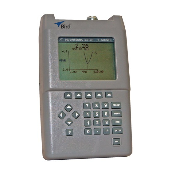
Page 14: Component Description
AT-800 Antenna Tester Component Description Figure 2 Component Description... - Page 15 Introduction LCD Display Backlit liquid crystal display. External DC Connect either the ac adapter or the cigarette lighter adapter cable. External Connector supplies operate the unit and charge the internal battery. Cursor Keys Left Arrow Press in swept frequency mode to move the cursor to the left.
-
Page 16: Display Description
AT-800 Antenna Tester Display Description Figure 3 Display Description... - Page 17 Introduction Sweep Rate Blinks when sweeping. Indicator Measurement Units Indicates selected measurement units. Trace Graphic display of measured results across selected frequency band. Menu Select Key Defines function of menu select keys located below the display. Labels Frequency Band Displays frequency band selected. Scale Cursor Used to select measurement...
-
Page 18: Features
AT-800 Antenna Tester Features Swept Frequency Mode — Fast scan shows Voltage Standing Wave Ratio (VSWR); Reflection Coefficient (); % Match, or Return Loss (dB) across an entire band. A movable cursor can be used to pinpoint a scan frequency and the corresponding measurement value is displayed. -
Page 19: Chapter 2 Basic Operations
Chapter 2 Basic Operations Getting Started This section describes initial quick steps to get started. For detailed information regarding connecting the Antenna Tester refer to "Connecting the Antenna" on page 14 Note: This unit is shipped with the batteries not charged. Charge batteries for at least 8 hours before use. - Page 20 Select Key The instructions in this manual are based on stepping through the software menu using the keys below the display. Once comfortable operating the AT-800, it may be faster to use the SELECT key to access some functions. These include: Units, Scale, Start and Stop Frequencies in swept frequency mode and Units, Scale, Frequency and Channel in single frequency mode.
-
Page 21: Messages
Basic Operations Messages There are five messages that are displayed to inform of equipment, or procedural, conditions. “Lo Batt” Displayed when battery voltage is less than 6.6V, refer to "Charging Batteries" on page 30 “Busy” Displayed during mode changes indicating the measurement information is being updated. -
Page 22: Setting The Auto Shut-Off Timer
AT-800 Antenna Tester Setting the Auto Shut-Off Timer In order to preserve battery life, the Antenna Tester will automatically shut off after 5,15,30 or 60 minutes without any keystrokes. Follow the steps below to select the length of time, before auto shut-off occurs. -
Page 23: Set Serial Baud Rate
Basic Operations Set Serial Baud Rate Measurement data can be transferred between the AT-800 and a personal computer using the serial port and optional interface software. The data can then be used for analysis, printed, or stored. The data transfer rate (baud rate) between the Antenna Tester and computer must be identical and set to 9600. -
Page 24: Chapter 3 Installation
"Component Description" on page 2 Power Supply The AT-800 can use an external power source. Using the ac adapter or the 12V cigarette lighter adapter cable will also charge the battery. Using the ac adapter, charge time is about 8 hours. Using the cigarette lighter adapter cable, charge time will depend on the car battery charge. -
Page 25: Automobile Cigarette Lighter Adapter Cable
Installation Automobile Cigarette Lighter Adapter Cable Note: Before inserting the adapter’s barrel connector into the Antenna Tester’s DC jack ( ), verify that the polarity of the Figure 4 adapter barrel is correct ( ). The negative (–) symbol must Figure 4 be adjacent to the word TIP as the center is negative and the out- side is positive. -
Page 26: Connecting The Antenna
At active sites, RF energy from transmitters can be coupled to the antenna under test. If large enough, these signals will cause inaccurate measurements. For best results, the AT-800 should be used with all transmit antennas powered down. -
Page 27: Chapter 4 Measure Match
User selections are customized, the power is on, and the top level menu is displayed (also in basic operation). Since the AT-800 changes the way antennas are tested, take some time to explore the different operating modes and find what is best for individual applications. -
Page 28: Band Selection Presets Vs. User Defined
AT-800 Antenna Tester Band Selection Presets vs. User Defined In swept frequency mode, band presets ensure the antenna system is tested at the correct frequencies. Selecting transmit (Tx), receive (Rx), or both (TxRx) automatically sets start and stop frequencies for the cellular system and base or mobile selections in the utility menu. -
Page 29: Auto Scale Vs. Manual Scale
Measure Match Auto Scale vs. Manual Scale In swept mode Auto Scaling sets the measurement unit scale to make the trace easier to read. However, for quick comparisons of the size or shape of traces, it might be more meaningful to set a standard scale. Note: It is possible to set the scale manually so the information is not on the display at all. -
Page 30: Sweep Type - Single Hold Vs. Continuous
AT-800 Antenna Tester Figure 9 Auto Scaling Single Frequency Mode Figure 10 Manual Scaling Single Frequency Mode Sweep Type – Single Hold vs. Continuous Continuous sweep continually sweeps the frequency band and updates the value after each sweep. An asterisk (*) blinks on the left side of the display to indicate sweep rate. -
Page 31: Swept Frequency
Measure Match Swept Frequency Select Frequency Band - Presets With the cellular system selected, the start and stop frequencies can be automatically selected for transmit (Tx), receive (Rx), or both (TxRx). 1. Press the MENU key. 2. Press the MEAS MATCH key. 3. -
Page 32: Select Measurement Units
AT-800 Antenna Tester Note: The tester will begin sweeping. Center MHz The cursor will blink on the Center frequency and Center MHz will be highlighted. Enter the frequency using the numeric keypad or change the frequency using the UP/DOWN arrow keys. -
Page 33: Selecting The Sweep Type
Measure Match Auto Scale The units scale changes and the Antenna Tester begins sweeping. Manual Scale The cursor will blink on the minimum scale value and Manual Scale will be highlighted. Enter the desired value using the numeric keypad or change the value using the UP/DOWN arrow keys. -
Page 34: Saving A Trace
AT-800 Antenna Tester Saving a Trace The AT-800 can store up to 12 traces. A saved trace can be used to evaluate long term antenna performance, to compare performance under different conditions or to compare to another antenna. A saved trace is also a powerful tool in limit testing. -
Page 35: Recalling A Trace
Measure Match Note: If registers 1-4 are full press the MORE SAVE key to access 5-8 and again to access 9-12. If needed, use the ESC key to back Note: It is a good idea to keep a record of which traces are in which register as they are identified by register number only. -
Page 36: Limit Testing
Limit testing is probably the most labor-efficient mode for operating the AT-800. Since all the software settings are retained when the tester is turned off, once the limit test is set up its simply a matter of connecting the next antenna system, turning on the power and reading pass or fail. -
Page 37: Using A Trace As The Limit
Measure Match 6. Enter the desired value using the numeric keypad or change the value using the UP/DOWN arrow keys. 7. Press the ENTER key. Note: Pass or Fail will be displayed, a tone will be heard for fail if audio is enabled. -
Page 38: Single Frequency
AT-800 Antenna Tester 3. Press the SWEPT FREQ key. 4. Press the LIMIT key. 5. Press the CLEAR LIMIT key. Note: The value field will change to off if an operator value was being used, the dotted outline of the limit trace will be removed if a trace was being used. -
Page 39: Select Auto Or Manual Scale
Measure Match 3. Press the SINGLE FREQ key. 4. Press the UNITS key. 5. Press either the RHO, VSWR, %MATCH or RETURN LOSS key. Note: The selected unit will be shown in the center of the display. 6. Press the RETURN key to go back one menu level. Select Auto or Manual Scale 1. -
Page 40: Chapter 5 Field Strength
Chapter 5 Field Strength Field Strength Measurement With the field strength antenna installed, the Antenna Tester can be used to verify the output of portable cellular phones with fixed antennas. This is a relative measurement. The measurement sensitivity is such that a full scale deflection will occur at about three meters from a source that is radiating 12.6 watts effective radiated power (ERP). -
Page 41: Chapter 6 Maintenance
Clean the antenna tester and the display with a soft cloth dampened with mild detergent and water only. Calibration For best performance and accuracy, the Antenna Tester should be calibrated once every 12 months. Return the unit to an authorized Bird Service Center. -
Page 42: Charging Batteries
AT-800 Antenna Tester Charging Batteries WARNING Care should be taken when handling batteries. Do not heat or dispose of batteries in fire. May burst or release toxic materials. Avoid forced discharge. Do not short circuit. Restrict charging current and time to the recommended value. -
Page 43: Operational Tests
The scale is set from 6-8V. If the voltage is less than 7V, the batteries should be changed. Note: The AT-800 will shut off if the battery is low, but it will maintain full accuracy at any battery voltage. -
Page 44: Display Test
Each pixel then changes state, either from black to white or white to black. If part of the display is not functional return the tester to Bird Electronic for repair. Figure 15 Display Test 1. -
Page 45: Self Test
Maintenance Self Test The self test is similar to the operational tests run at power up described on , except for the keypad test. "Power-up" on page 31 Figure 16 Self Test 1. Press the MENU key. 2. Press the TEST key. 3. -
Page 46: Battery Replacement
AT-800 Antenna Tester Battery Replacement The batteries need to be replaced when fully charged batteries provide less than 2 hours operation. Carefully follow the instructions below to replace the batteries. For models equipped with 700 mAh Nickel-Cadium batteries (p/n 5A2230): Note: Unit may contain six 700 mAh Nickel-Cadium (NiCAD) bat- teries. -
Page 47: Fuse Replacement
Maintenance Fuse Replacement CAUTION Replace with only the same type and rating fuse. 315mA 250V Follow the steps outlined in Battery Replacement replacing the fuse where replacing the batteries is indicated. Figure 17 Battery / Fuse Replacement... -
Page 48: Troubleshooting
Troubleshooting Operator maintenance or service is limited to battery and fuse replacement. Any other required service must be performed at an authorized Bird Service Center. Refer to the following paragraphs for help in isolating error conditions. The Antenna Tester will not power up Power for the Antenna Tester can be provided in three ways—the internal... -
Page 49: Antenna Tester Indicates A Perfect Match
Antenna-Under-Test. If sufficiently strong, the interfering signals can over-power the measurement signal inside the Antenna Tester. Normally, this results in degraded measurement accuracy. Bird Antenna Testers minimize this effect by measuring the interfering signal during the time between match measurements. -
Page 50: Parts List
AT-800 Antenna Tester Parts List Part Name Part Number AT-800 Complete 7000A801 Parts Supplied with AT-800 Complete, or installed when shipped. 5A2230 (in older models) Battery (6 required) 5B2230 (in newer models) Fuse RP5-1976-11 AC Mains Adapter 115v 5A2229 230v... -
Page 51: Specifications
Maintenance Specifications Frequency Range 806 to 960 MHz Frequency Resolution 30 kHz Measurement Range VSWR 1.00 to 100.00 Match Efficiency 0 to 100% Return Loss -32 to 0 dB 0.000 to 1.000 Measurement Speed (Typical) Single Frequency 5 Readings/second Swept Frequency 1 Sweep/second Test Port ... -
Page 52: Menu Structure
AT-800 Antenna Tester Menu Structure... -
Page 53: Limited Warranty
Limited Warranty All products manufactured by Seller are warranted to be free from defects in material and workmanship for a period of one (1) year, unless otherwise specified, from date of shipment and to conform to applicable specifications, drawings, blueprints and/or samples. Seller’s sole obligation under these warranties shall be to issue credit, repair or replace any item or part thereof which is proved to be other than as warranted;...
Need help?
Do you have a question about the AT-800 and is the answer not in the manual?
Questions and answers