Table of Contents
Advertisement
Air-conditioner Control System
BM ADAPTER
Model: BAC-HD150
Thoroughly read this installation manual before
use to ensure safety. The users should keep this
manual for future reference and refer to it as
necessary.
BACnet™ is a registered trade mark of ASHRAE
(American Society of Heating, Refrigerating, and
Air-Conditioning Engineers, Inc.).
Installation Manual
Contents
Safety Precautions............................................ 2
1.
Specifications............................................ 4
1-1. Product Specifications ..................... 4
1-2. External dimensions......................... 4
transmission line .............................. 5
2.
Sample system configuration.................... 6
3.
Installation................................................. 9
3-1. Required parts ................................. 9
3-2. M-NET transmission line length ..... 10
3-3. Installation...................................... 11
4.
Wiring connections.................................. 12
cover .............................................. 12
lines................................................ 13
4-4. Connecting the LAN cable ............. 14
5.
Making the initial settings........................ 14
6.
Test run................................................... 14
Page
Advertisement
Table of Contents

Related Manuals for Mitsubishi Electric BAC-HD150


Summary of Contents for Mitsubishi Electric BAC-HD150
-
Page 1: Table Of Contents
Air-conditioner Control System BM ADAPTER Model: BAC-HD150 Installation Manual Contents Page Safety Precautions..........2 Specifications..........4 1-1. Product Specifications ..... 4 1-2. External dimensions......4 1-3. Power supply function to the M-NET transmission line ......5 Sample system configuration....6 Installation.......... -
Page 2: Safety Precautions
Safety Precautions • Thoroughly read the following safety precautions prior to installation. • Observe these precautions carefully to ensure safety. WARNING Indicates a risk of death or serious injury. CAUTION Indicates a risk of injury or structural damage. • After reading this manual, pass the manual on to the end user to retain for future reference. •... - Page 3 General caution Do not install the unit in environments where large Wear protective gloves. amounts of oil (including machine) or acidic/alkaline A high voltage is applied to the terminals. To reduce the risk of chemical sprays are present. These types of substances electric shock, wear protective gloves before touching the may cause device performance to be reduced and cause electrical parts on the unit.
-
Page 4: Specifications
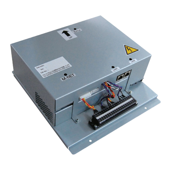
Inside the control panel (indoor) 1-2. External dimensions Unit: mm (in) 250(9- 97.2(3- 155(6- Terminal block (to be used in the future when functions of the BAC-HD150 are upgraded.) M-NET Terminal Power source 100-240 VAC block (M3.5) Terminal block (M3.5) LAN1... -
Page 5: Power Supply Function To The M-Net Transmission Line
BAC-HD150 has a built-in function to supply power to the M-NET transmission line. (power supply coefficient: 6) When power is supplied from BAC-HD150, the types of system controllers listed in the table below are connectable. Table 1 Power consumption coefficient of the controller... -
Page 6: Sample System Configuration
The figure below only shows the transmission line connections. Power supply lines are omitted. Building management system Indoor unit Local remote controller BACnet (LAN) Mitsubishi Electric air conditioning system M-NET transmission line K transmission line BM ADAPTER Model: BAC-HD150 MA remote controller line... - Page 7 Refer to the K-transmission converter Installation manual for details. 1 Be sure to set the BAC-HD150 address to "000." 2 Be sure to set the K-control air conditioning unit connection setting on the BAC-HD150 to Yes (set via the Setting Tool).
- Page 8 Note The system cannot be configured in the following way. Groups that are not under the control of a main SC cannot be controlled from a sub SC. Main SC Sub SC Group Group Group Each group cannot be under the control of two or more main SC. Main SC 1 Main SC 2 Group...
-
Page 9: Installation
3 Installation 3-1. Required parts The following parts are required to install the unit. Required parts Specification Power cable/ Power supply cable of appliances shall not be lighter than design 245 IEC 57 or 227 IEC 57. Protective earth cable Cable size:0.75mm²... -
Page 10: M-Net Transmission Line Length
3-2. M-NET transmission line length • Connect the BAC-HD150 to the transmission line for centralized control (TB7 on the outdoor unit). • There should only be one power supply source within a single transmission circuit. The factory setting is that power is not supplied from the BAC-HD150. -
Page 11: Installation
3-3. Installation • Leave enough space around the unit to allow for an installation/uninstallation of the cover. • Screw down the cover with M4 screws as shown in the figure below. Be sure to fix the four corners to prevent it from falling. •... -
Page 12: Wiring Connections
Use a bipolar breaker (2P2E) with a minimum contact distance of 3 mm ( in). • Install a breaker for each BAC-HD150 so that turning off the power to one BAC-HD150 will not affect the rest of the devices in the system. -
Page 13: Connecting The M-Net Transmission Lines
(non-polarized) Cable Shield clamps (2) To not supply power to the M-NET transmission line from the BAC-HD150 Connect the M-NET transmission lines and the power jumper as shown in the figure below. Power supply unit (PAC-SC51KUA...etc) Outdoor unit BM ADAPTER... -
Page 14: Connecting The Lan Cable
4-4. Connecting the LAN cable • Make sure that the LAN cable is long enough to reach the LAN1 connector on the BAC-HD150. Leave the LAN cable disconnected until all the initial settings for the BAC-HD150 (IP address setting etc.) have been completed. - Page 15 NOTE: This equipment has been tested and found to comply with the limits for a Class B digital device, pursuant to Part 15 of the FCC Rules. These limits are designed to provide resonable protection against harmful interference in a residential installation. This equipment generates, uses and can radiate radio frequency energy and, if not installed and used in accordance with the instructions, may cause harmful interference to radio communications.
- Page 16 Please be sure to put the contact address/telephone number on this manual before handing it to the customer. HEAD OFFICE: TOKYO BLDG. , 2-7-3, MARUNOUCHI, CHIYODA-KU, TOKYO 100-8310, JAPAN Authorized representative in EU: MITSUBISHI ELECTRIC EUROPE B.V. HARMAN HOUSE, 1 GEORGE STREET, UXBRIDGE, MIDDLESEX UB8 1QQ, U.K. WT05543X01...
Need help?
Do you have a question about the BAC-HD150 and is the answer not in the manual?
Questions and answers