
Related Manuals for CMP DEL AOP 50


Summary of Contents for CMP DEL AOP 50
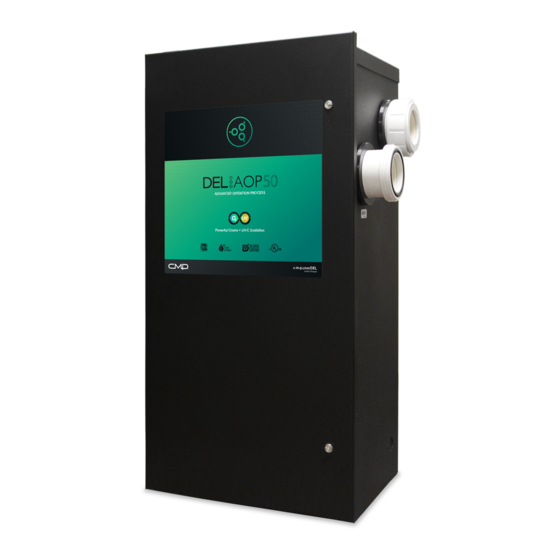
- Page 1 DEL AOP 50 INSTALLATION INSTRUCTIONS & PRODUCT MANUAL C-M-P.COM/DEL 4-2305-01 Rev.E...
- Page 2 Figure 3. Install to provide water drainage of generator to protect electrical components. • Mount the DEL AOP 50 so that it is inaccessible to anyone in the pool. Never attempt any servicing while unit is wet.
- Page 3 • Short-term inhalation of high concentrations of ozone WARNING and long term inhalation of low concentrations of ozone can cause serious harmful physiological effects. DO NOT inhale ozone gas produced by this device. • For your safety, do not store or use gasoline, chemicals or other flammable liquids or vapors near this or any other appliance.
-
Page 4: Table Of Contents
TABLE OF CONTENTS SECTION 1 General Information 1A. Description ................. 1 1B. Specifications ................1 SECTION 2 Installation 2A. Pool Preparation ..............2 2B. Location ..................2 2C. Mounting ................... 3 2D. Electrical ..................3 2E. Plumbing ..................4 SECTION 3 Operation 3A. - Page 5 TABLE OF CONTENTS SECTION 4 Maintenance & Service 4A. System Electromechanical Overview ......... 7 4B. System Maintenance .............. 9 4C. Ozone Module Servicing ............9 4D. UV Reactor Service & Maintenance ......... 11 SECTION 5 Troubleshooting 5A. Troubleshooting ..............15 SECTION 6 Contact Information 6A.
-
Page 6: Section 1 General Information
Section 1 General Information 1A. Description The DEL AOP 50 Ozone and UV Sanitizer System described in this manual is designed to provide the benefits of ozonated and UV treated water in an environmentally safe and effective manner. The high quality, specially engineered components ensure efficient water sanitation output and reliable performance. -
Page 7: Section 2 Installation
2B. Location The DEL AOP 50 unit is designed for floor mounting. Locate the unit in a clean, protected area, either indoors or outdoors (preferably out of direct sunlight). If possible, locate the unit out of reach of sprinklers or drainage spouts. -
Page 8: Mounting
2D. Electrical 2D-1. Main Power Connect the DEL AOP 50 to the pool timing clock so that the DEL AOP 50 operates simultaneously with the pool pump. The DEL AOP 50 has four available Knockouts for a 1/2” conduit fitting, two on the back and one on each side. -
Page 9: Plumbing
Appendix A. The DEL AOP 50 will come with one half of a union fitting installed on Inlet and Outlet, the other half of the fittings will be located in the DEL AOP 50 parts bag. -
Page 10: Section 3 Operation
To remove the bubbles from the flow, an accessory Mixing Degas Vessel, or MDV, can be installed downstream of the DEL AOP 50. The MDV-100 is designed for use with the DEL AOP 50 and is recommended on indoor, covered, or vinyl-lined pools. -
Page 11: Normal Operation
3B. Normal Operation Indicator Lights: The DEL AOP 50 has two external indicator lights, red and green, on its left side. When the DEL AOP 50 has power, the green Power Light will illuminate. The red Flow Indicator may be on momentarily. -
Page 12: Water Chemistry
4A-2. Ultraviolet Lamps There are two lamps in the UV Reactor of the DEL AOP 50. If the UV Lamp Access Panel is removed while the unit is running, a slight glow can be seen near the top of the lamps (Refer to Figure 6 for a more detailed view). - Page 13 Section 4 Maintenance & Service FLOW SWITCH RELAY NOTE: BALLAST LOCATED ON ENCLOSURE CEILING NOT SHOWN OZONE GENERATOR ASSEMBLY FLOW SWITCH OZONE GAS LINE INJECTOR MANIFOLD UV REACTOR INJECTOR TUBE DEL CHECK VALVE ADAPTER Figure 4: DEL AOP 50 Electro-Mechanical Overview 4A-5. Ozone Module Filters and Orifice The air entering the Ozone Modules passes through individual Filters and an Orifice on each Module inlet.
-
Page 14: System Maintenance
4B. System Maintenance Use a size 2 phillips driver to remove the UV Access Panel or a flat tool to open the Enclosure Cover as needed. NOTE: The DEL AOP 50 will not operate until the UV access panel is replaced. 4B-1. Ozone Module Maintenance The green Ozone Module Lights on the Ozone Modules indicate that the Ozone Power Supply is operating properly. - Page 15 BLOCK Figure 5: Ozone Generator Subassembly 4C-2. Replacing an Ozone Module 1. Open the DEL AOP 50 as described in SECTION 4C-1. 2. Locate the Ozone Modules on the left wall of the enclosure. 3. Remove the Filter Cap Assembly from the right tube fitting of the Ozone Module. Make sure you keep the Cap, Filter and Orifice together.
-
Page 16: Uv Reactor Service & Maintenance
Reactor every six (6) months and cleaned if necessary. Figure 6: Ozone Bracket During Ozone Module Service 4D-1 Lamp Removal 1. Locate the UV Lamp Access Panel on the top of the DEL AOP 50, remove the 4 screws with a Phillips head screwdriver, and remove the panel. 2. After allowing adequate time for the lamps to cool, disconnect the Lamp Connectors from Ballast wires. - Page 17 NOTE: For instructions on cleaning without mechanical disassembly, see Appendix D. NOTE: If the DEL AOP 50 is installed below water level, the bypass valves must all be CLOSED to prevent excess pool water from draining into the open unit when a Quartz Tube is removed.
- Page 18 Section 4 Maintenance & Service Follow the directions for use and handling of muriatic CAUTION acid on the acid bottle label, being careful to protect your eyes, wear rubber gloves, and avoid breathing acid fumes. NOTE: DO NOT USE ABRASIVE CLEANERS as they can scratch the high quality quartz glass.
- Page 19 Section 4 Maintenance & Service PROPERLY SEATED QUARTZ IMPROPERLY TUBE SEATED QUARTZ TUBE Figure 8: UV Quartz Tube Installation 4D-4 Re-installing the UV Lamp(s) NOTE: Make sure to handle the UV lamp as described in SECTION 4D-1. 1. TURN OFF YOUR PUMP IF YOU HAVE NOT DONE SO. 2. Slowly press the UV Lamp fully past the Lamp Retainer tabs and into the Quartz Tube until it is seated on the Lamp Cushion in the bottom of the tube.
-
Page 20: Section 5 Troubleshooting
SECTION 6A). Symptom: Green Indicator not lit when pool system is on. 1. No power to the DEL AOP 50 from the Power Source: a. Check circuit breaker at the power distribution box. b. Check for loose connections or wiring breaks in the lines leading to the Terminal Block. -
Page 21: Section 6 Contact Information
Section 6 Contact Information 6A. Contact Information: For technical assistance: • Call: 1 (800) 676-1335 • Email: o3info@delozone.com • Or visit our website: www.delozone.com Be prepared with the following information: • Name • Address • Model # • Date Purchased 6B. Ordering Information: To locate a dealer nearest you call 1 (800) 676-1335 or visit www.delozone.com. -
Page 22: Appendix A: Installation Plumbing
APPENDIX A... - Page 23 APPENDIX A DEL AOP 50 Installation - Plumbing The DEL AOP 50 works under vacuum. The injector in the DEL AOP 50 draws the ozone/air gas mixture from the ozone cells and mixes it into the water leaving behind some un-dissolved gas bubbles. These bubbles can affect certain pool system components, so care must be taken when installing the DEL AOP 50.
-
Page 24: Appendix B: Ozone Cell Cleaning
Ozone Manifold and Air Inlet Filters. • Leave the DEL AOP 50 disconnected and run the pool circulation system. Allow fresh air to be pulled through the cells for 10 minutes. • Close or reattach the DEL AOP 50 cover and reconnect power. - Page 25 APPENDIX B Syringe Discharge tube to recovery container Figure 2. Rinsing the Ozone Cell Remove Ozone Outlet Manifold Remove Air Inlet Filters Figure 1. Ozone Generator Assembly...
-
Page 26: Appendix C: Pressure Drop Curve
APPENDIX C DEL AOP 50 Pressure Drop Characterization NOTE: Tested on simulated recirculation system using a Pentair Intelliflo variable speed pump. No back pressure added. Back pressure will raise the inlet pressure (filter pressure) but reduce the pressure drop slightly. Actual results will vary depending on pump and plumbing variables. -
Page 27: Appendix D: In-Place Quartz Tube Cleaning
The DEL AOP 50 Quartz Tubes may be cleaned without removing them from the vessel. Ensure that the DEL AOP 50 is isolated from the rest of the pool system with valves at the inlet and outlet (as shown in Figure 3). - Page 28 CMP , LLC 36 HERRING ROAD, NEWNAN, GA 30265 WWW.C-M-P .COM/DEL 0118lm...
Need help?
Do you have a question about the DEL AOP 50 and is the answer not in the manual?
Questions and answers