Advertisement
black & white
®
WARNINGS AND CAUTIONS
• TO AVOID FIRE, SHOCK OR DEATH; UNPLUG CORD OR TURN OFF POWER at circuit breaker or fuse and test that power is off before wiring!
• To be installed and/or used in accordance with appropriate electrical codes and regulations.
• If you are unsure about any part of these instructions, consult an electrician.
• Use this device with copper or copper clad wire only.
1. Loosen assembly screws and separate device module from husk. If needed, back out cord clamp screws enough to allow cord to fit between the clamp and husk and remove clamp
insert if necessary as per gage on device. Insert cord through husk (refer Wiring Diagram).
2. Strip cord jacket, if applicable, according to Wire Stripping diagram. Strip insulation to expose 9/16" (1.42 cm) bare copper at end of each conductor (per wire stripping diagram or strip
gage on device).
3. NOTE: TERMINAL SCREW POLARITY IS DESIGNATED BY SCREW COLOR (refer to Wiring Chart). Fully back out terminal screws. Connect wires per WIRING DIAGRAM as
follows: BLACK (Hot) wire to BRASS screw, WHITE (Neutral) wire to SILVER screw, and GREEN or GROUND wire to GREEN screw (refer to Wiring Diagram and Wiring Chart).
Twist all strands of each conductor tightly together (DO NOT TIN CONDUCTORS). Insert conductors into appropriate wire well and tighten terminal screws firmly to 10-14 in-lbs.
CAUTION: COPPER CONDUCTORS MUST BE FULLY INSERTED INTO WIRE WELLS. CUT OFF ANY STRAY STRANDS. TERMINAL CLAMPS MUST TIGHTEN ONTO WIRE
CONDUCTOR ONLY. BE SURE NOT TO INCLUDE INSULATION WHEN TIGHTENING TERMINAL CLAMPS.
Refer to NEC tables, Article 400 (or local equivalent) for proper wire type and size for your application and load.
4. Reattach device body to housing by aligning key (refer to Wiring Diagram). Tighten assembly screws. Firmly secure cord clamp onto husk by alternately tightening cord clamp screws
to 12-14 in-lbs. The strain relief will accommodate cords from SVT #18-3 to ST #10-3 (0.25" to 0.70" outer diameter), with a maximum of SO #14-3 using strain relief insert.
WIRING CHART / TABLEU DE CÂBLAGE / CUADRO DE CABLADO
Rating
125 & 277 VAC
Valeurs nominales
125 et 277 V c.a.
Capacidad
125 y 277 VCA
Ground
Terre
Tierra
Neutral
Neutre
Neutro
Hot
Actif
Fase
Neon Lamp
Lampe au néon
Lámpara de Neón
FOR CANADA ONLY
For warranty information and/or product returns, residents of Canada should contact Leviton in writing at Leviton Manufacturing of Canada ULC to the attention of the Quality
Assurance Department, 165 Hymus Blvd, Pointe-Claire (Quebec), Canada H9R 1E9 or by telephone at 1 800 405-5320.
Leviton warrants to the original consumer purchaser and not for the benefit of anyone else that this product at the time of its sale by Leviton is free of defects in materials and workmanship under normal and
proper use during the lifetime of the product. Leviton's only obligation is to correct such defects by repair or replacement, at its option. For details visit www.leviton.com or call 1-800-824-3005. This warranty
excludes and there is disclaimed liability for labor for removal of this product or reinstallation. This warranty is void if this product is installed improperly or in an improper environment, overloaded, misused,
opened, abused, or altered in any manner, or is not used under normal operating conditions or not in accordance with any labels or instructions. There are no other or implied warranties of any kind, including
merchantability and fitness for a particular purpose. Leviton is not liable for incidental, indirect, special, or consequential damages, including without limitation, damage to, or loss of use of, any
equipment, lost sales or profits or delay or failure to perform this warranty obligation. The remedies provided herein are the exclusive remedies under this warranty, whether based on contract, tort or otherwise.
© 2019 Leviton Mfg. Co., Inc.
Black & White
Lighted Plugs & Connectors
250 VAC
250 V c.a.
250 VCA
Green
Green
Vert
Vert
Verde
Verde
White
---------------
Blanc
---------------
Blanco
---------------
Brass
Brass
Laiton
Laiton
Laton
Laton
Brass
Laiton
Laton
General Wiring Diagram for Plugs & Connectors
Schéma général de câblage pour fiches et connecteurs
Diagrama General de Cableado de los Conectores y Clavijas
Cord Clamp
Bride du cordon
Abrazadera
Strain Relief Insert
Garniture de collier
Inserto contra tirones
Husk
Coquille
Bastidor
Wire Well
Orifice de câblage
Orificio de Cableado
Module
Module
Módulo
Assembly Screws
Vis d'assemblage
Tornillos de Ensamble
LIMITED LIFETIME WARRANTY AND EXCLUSIONS
For Technical Assistance Call: 1-800-824-3005 (USA Only) or 1-800-405-5320 (Canada Only) www.leviton.com
®
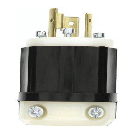
Locking & Straight Blade,
Rating: 15A and 20A
INSTALLATION
Cord Jacket
Gaine du cordon
Forro del Cordón
Brass or "HOT" Terminal Screw (X)
Borne laiton ou active (x)
Tornillo terminal Latón o "Fase" (X)
Wiring Stripping Diagram
Schéma de dénudage
Diagrama de Pelado
Insulation
Isolant
Aislante
9/16"
(1.42 cm )
15/16"
(2.38 cm )
Key Aligning Device (not shown)
Patte d'alignement
Llave guía (no se ve)
Green Hex Ground Screw
Vis de terre hexagonale verte
Tornillo Verde a Tierra Hexágano
Brass or "HOT" Terminal Screw (Y)
Borne laiton ou active (Y)
Tornillo terminal Latón o "Fase" (Y)
PK-A3150-10-02-0G
ENGLISH
Copper Strands
Brins de cuivre
Hilos de Cobre
PK-A3150-10-02-0G
Advertisement
Table of Contents

Related Manuals for Leviton Black & White 2311-PLC


Summary of Contents for Leviton Black & White 2311-PLC
- Page 1 LIMITED LIFETIME WARRANTY AND EXCLUSIONS Leviton warrants to the original consumer purchaser and not for the benefit of anyone else that this product at the time of its sale by Leviton is free of defects in materials and workmanship under normal and proper use during the lifetime of the product.
- Page 2 Leviton garantit au premier acheteur-consommateur (ci-après désigné par le terme « Acheteur »), et uniquement au crédit du dit Acheteur, que ce produit ne présente ni défauts de fabrication ni défauts de matériaux au moment de sa vente par Leviton, et n’en présentera pas, tant qu’il sera utilisé de façon normale et adéquate, pendant toute la durée utile du produit. La seule obligation de Leviton sera de corriger les dits défauts en réparant ou en remplaçant le produit défectueux, à...
Need help?
Do you have a question about the Black & White 2311-PLC and is the answer not in the manual?
Questions and answers