
Related Manuals for Behncke EWT 95-15


Summary of Contents for Behncke EWT 95-15
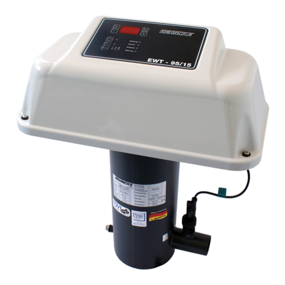
- Page 1 Installation Instruction Electric Heat Exchanger Electric/Swimming Pool Water EWT 95 - 15 Your BEHNCKE ® Specialist Dealer – Subject to technical alteration! – Stand 03/2011...
- Page 2 ® GmbH has produced high-quality pro- ducts for the public and private swimming pool and whirlpool sector for more than 30 years. Your Behncke ® specialist dealer will always give you advice and support. Please read this installation instruction with great care.
-
Page 3: Table Of Contents
Inhaltsverzeichnis Table of contents 1 Safety Risks When Handling Electric Heat Exchanger Safety Instructions and Information Intended Use Sources of Danger Safety Measures on the Installation Site Safety Equipment 2 Technical Data EWT 95 - 15 3 Set-up/Installation Transportation/Storage Set-up and Installation Dimensions Set-up Installation Water Connection... -
Page 4: Safety
Safety Safety Risks When Handling Electric Heat Exchanger The electric heat exchanger has been built on the basis of state-of-the-art techno- logy and the approved safety-technical guidelines. Nevertheless, risk might occur during use such as - violation of operator or - third parties - impairments in electric heat exchanger or - damage to other material values. -
Page 5: Intended Use
The electric heat exchanger is exclusively designed for heating bathwater with acti- vated recirculating or filter pump. Any other mode of application is not regarded as intended use. The manufacturer Behncke ® GmbH is not liable for any resulting damage. -
Page 6: Sources Of Danger
Safety Sources of Danger The electric heat exchanger can be damaged. If the maximum operational pressure of 3.0 bar is exceeded, the electric heat exchanger might develop leaks. take care The risk of burns exist. The connections and the electric heat exchanger might reach temperatures of up to 100°C. -
Page 7: Technical Data
Technical Data Technical Data EWT 95 - 15 Article Power in KW Supply Temperature Article No. Voltage Selection in Volt in °C EWT 95 -15 230/400 – 302 051 18 EWT 95 -15 230/400 – 302 051 27 EWT 95 -15 230/400 –... -
Page 8: Set-Up/Installation
Set-up/Installation Set-up/Installation Transportation/Storage Transport the electric heat exchanger only after it has been drained. Store the flushed and drained electric heat exchanger in interior rooms with non-aggressive atmosphere only. Set-up and Installation Dimensions Article Kombi Socket d50/1 1 / EWT 95 -15 ”... -
Page 9: Set-Up
Set-up/Installation Set-up Set up the electric heat exchanger in frost-proof and dry rooms with non-agressive atmosphere only. Dripping water might damage the electric heat exchanger. Ensure easy access for installation and removal purposes. The following water values are to be observed for the electric heat exchanger. EWT 60-20/30 Chloride contents max. -
Page 10: Water Connection
Set-up/Installation Water Connection 3.5.1 Installation Layout Above the Water Level Figure: horizontal installation 3.5.2 Installation Layout Below the Water Level Figure: horizontal installation... -
Page 11: Electrical Connection
(30 mA). All metal parts are to be integraded into equipotential bonding. It ist absolutely recommended to built in a main protection (circuit diagramm, cap. 9). By switching of the safety temperature limiter the EWT 95-15 is completely switched off. -
Page 12: Funcional Course
Functional Course Functional Course In the electric heat exchanger, heat is transferred to the bathwater through the heating element. The thermostat regulates the water temperature in accordance with the adjusted value, range from 4 to 40°C. By pressing the I/O Button the EWT can be reseted after a breakdown. (LED Störung is on) The safety temperature limiter protects from overheating. -
Page 13: Service Control Unit
Service control unit Service control unit Event Symbol description Pressing button O/I Unit is switched ON/OFF Display shows AUS if the unit is off Unit ON without Display shows - 0 - FP-running (FP=filter pump) Unit ON with Display shows the actual FP-running temperature of swimming (FP=filter pump) - Page 14 Service control unit Pressing buttons + and - If the buttons + and – are pressed synchronous for 10 sec., display is flashing and the actual value can be calibrated. Pressing button AUTO If the button AUTO is pressing the heating power degree is automatically selected Pressing button HAND If the button HAND is pressing...
- Page 15 Service control unit Degree III is shining Heating of Water by heating power degree III Display shows - 0 - Cuurent ok, controller ok, filter pump not running. Display shows FP Filter pump is switched offlt runs the running after time the filter pump to avoid heating dam*.
-
Page 16: Initial Operation
Initial Operation, Maintenance/Repair Initial Operation Have you read and understood these operating instructions – in particular chapter 1, Safety? Only then are you allowed to start the electric heat exchanger. • Adjust the desired bathwater temperature in the thermostat The electric heat exchanger heats the bathwater as long as the adjusted tempera- ture has not been reached, The electric heat exchanger can be damaged. -
Page 17: Hibernation Of The Ewt In Non Frost-Proof Rooms
Maintenance/Repair Hibernation of the EWT in Non Frost-proof Rooms Expert Hibernation without frost damage is possible if the following steps are observed: • Close blocking units in the water cycle (the blocking units must be installed in frost-free rooms) • Flush and drain electric heat exchanger and adjoining pipes until blocking units. 7.2.1 Electric Heat Exchanger with Horizontal Layout •... -
Page 18: Troubleshooting
Troubleshooting Troubleshooting Effects Checking the possible cause No performance is te electric heat exchanger connected to the electrical supply? have the blocking units been opened? is the electric heat exchanger completely filled with water? has the electric heat exchanger been ventilated? is there sufficient flow (see Technical Data) in the electric heat exchanger? Electric heat... -
Page 19: Circuit Diagram
Cirquit Diagram Cirquit Diagram Connection with Kombi Filter controlling... -
Page 20: Connection Without Kombi Filter Controlling
Cirquit Diagram Connection without Kombi filter controlling... -
Page 21: Explosion Drawings And Piece Lists
Explosion Drawings and Piece Lists Explosion Drawings and Piece Lists Figure: Explosion Drawing EWT 95 - 15... -
Page 22: Piece List Ewt
Explosion Drawings and Piece Lists 10.1 Piece list EWT 95 - 15 Item Piece Article Designation Article No. Housing upper part 302.050.00 Housing lower part 302.050.01 Controller 302.050.10 Seal f. controller 302.050.06 Seal f. Housing lower part 302.050.05 Seal f. Housing 302.050.07 Heating element 6 KW / 400 V –Incoloy- f. - Page 23 – EMV- (electromagnetic compatibility) Norm 2004/108/EG Electric heat exchanger Product Behncke Manufacturer ® GmbH EWT 95-15 Type Maschine No. Year of construction The Declaration of Conformity was developed, designed and produced, in accordance with the above-mentioned guidelines, by Behncke ®...
- Page 24 BEHNCKE GmbH Bayern: Michael-Haslbeck-Straße 13 D-85640 Putzbrunn/München Phone: + 49 (0) 89/ 45 69 17-0 Fax: + 49 (0) 89/46 85-11 Sachsen-Anhalt: Stötterlinger Straße 36 a D-38835 Bühne Phone: + 49 (0) 3 94 21/7 96-0 Fax: + 49 (0) 3 94 21/7 96-30 info@behncke.com...
Need help?
Do you have a question about the EWT 95-15 and is the answer not in the manual?
Questions and answers