
Subscribe to Our Youtube Channel
Related Manuals for Mueller Falling Film Chiller


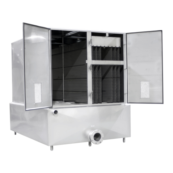
Summary of Contents for Mueller Falling Film Chiller
- Page 1 Falling Film Chiller INSTALLATION AND OPERATION MANUAL Part No. 9843514 Effective February 12, 2003 Revised March 17, 2020...
-
Page 3: Table Of Contents
Mueller Multi-Stage Chiller Cooling and Pump Control ........ - Page 4 Figure 5: Wiring Schematic ....................17 Mueller Falling Film Chiller Effective February 12, 2003 Installation and Operation Manual, Part No.
-
Page 5: Section 1.0 - Introduction
Section 1.0 – Introduction GENERAL INFORMATION This manual provides the basic information necessary to install, startup, and operate a Mueller® falling film chiller. Please contact Paul Mueller Company for additional technical assistance. Paul Mueller Company 1600 West Phelps Street Springfield, Missouri 65802... -
Page 6: Model 3 X 5 Dimensions
(in) (in) (in) Top Door (in) (lb) Top Door (in) 2–8 plate cabinet 68.5 39.13 97.13 99.63 Refrigerant plate Glycol plate Mueller Falling Film Chiller Effective February 12, 2003 Installation and Operation Manual, Part No. 9843514 Revised March 17, 2020... -
Page 7: Model 4 X 8 Standard Features
• A clamp-type ferrule and male pipe-thread adapter are included for the inlet. • Falling film chiller expansion valves for each refrigeration plate are available. • Refrigeration capacity and refrigerant type must be specified at the time of order. A. Required Water Flow Rates... -
Page 8: Model 4 X 8 Dimensions
9–16 plate cabinet 108.75 75.88 61.44 63.59 1,041 1,024 17–24 plate cabinet 108.75 109.13 61.44 63.59 1,444 1,419 Refrigerant plate Glycol plate Mueller Falling Film Chiller Effective February 12, 2003 Installation and Operation Manual, Part No. 9843514 Revised March 17, 2020... -
Page 9: Plate Design
PLATE DESIGN Paul Mueller Company manufactures plates for the falling film chiller in two basic styles. Figure 1 shows the plate used for direct expansion or recirculated refrigeration systems. Figure 2 shows the plate used for flooded refrigeration systems. FIGURE 1: PLATE DESIGN FOR DIRECT EXPANSION... -
Page 10: Falling Film Chiller Refrigerant Volumes
FALLING FILM CHILLER REFRIGERANT VOLUMES MODEL 3 X 5 No. of Plates Lbs. of R-22 @ 25°F Lbs. of R-717 @ 25°F Lbs. of R-507 @ 25°F MODEL 4 X 8 No. of Plates Lbs. of R-22 @ 25°F Lbs. of R-717 @ 25°F Lbs. -
Page 11: Model Number Breakdown
M = 1430 (25–32 4 x 8) N = 150 (2–8 3 x 5) O = 345 (2–8 3 x 5) Mueller Falling Film Chiller Effective February 12, 2003 Installation and Operation Manual, Part No. 9843514 Revised March 17, 2020... -
Page 12: Section 2.0 - Installation
LOCATION AND LEVELING THE CHILLER A. Location Locate the falling film chiller as close as practical to the process and to the condensing units. A drain should be close by for draining the chiller. Consider ease of disassembly for cleaning and the possible future addition of more vertical evaporator plates when selecting a location for the falling film chiller. -
Page 13: Locating Refrigeration Units
Chilled water line (see Table 2.13 for the recommended chilled water line size). • Adapter, tri-clamp to pipe thread. The 2" adapter is Mueller Part No. 9840758; the 2" is Part No. 9840759; the 4" is Part No. 9819684; and the 6" is Part No. 9841439. -
Page 14: Liquid Line Solenoid Valve
LIQUID LINE SOLENOID VALVE The Mueller condensing unit is designed to start and stop based on water temperature. It is not designed as a pump-down system. For proper operation of the falling film chiller it is necessary to install a liquid line solenoid valve to prevent refrigerant migration during down time. -
Page 15: Connecting The Overflow Line
2.10 MUELLER MULTI-STAGE CHILLER COOLING AND PUMP CONTROL If a Mueller multi-stage chiller cooling and pump control was purchased, please reference the multi-stage chiller control manual for installation and setup procedures. A crucial step in the installation of the multi-stage chiller control is the location of the temperature sensors. A rise in water temperature inside the chiller’s distribution pan will turn on Stage 1 and the condensing unit. -
Page 16: Setting Chiller Recirculation Flow And Water Makeup Flow
The idea behind the falling film chiller is that when the chiller calls for makeup water, the sensor sees the rise in temperature as the water enters the pan. -
Page 17: Cleaning The System
IMPORTANT: In rare cases, it is possible for chlorine gas to escape from the water as it passes over the falling film chiller. If this occurs, red rust will begin to form inside the chiller on the areas that are not constantly wet. - Page 18 This cross flow of air will remove the gas from the interior of the chiller. If it is necessary to clean the chiller due to rusting, a #2 metal conditioner is recommended. Contact Paul Mueller Company’s Service Department at 1-800-756-5991 or DFETechService@paulmueller.com for further technical assistance and recommendations.
- Page 19 Do not allow the compressor’s superheat to get above 40°F. Monitor the compressor discharge temperature, not allowing it to exceed 200°F. The compressor superheat adjustment will be discussed in Section 3.4. Mueller Falling Film Chiller Effective February 12, 2003 Installation and Operation Manual, Part No. 9843514...
- Page 20 Four fan units are duplex design and fans are cycled in pairs. FIGURE 4: CONDENSING UNIT SCHEMATIC IMPORTANT: The condensing unit schematics are for operational reference only. Please contact Paul Mueller Company’s Refrigeration Products division for unit specific schematics. Condenser Subcooler...
- Page 21 TF1: Control Transformer Identifies Terminal Blocks Factory Wired Field Wired CR0060 24 V CONTROL VOLTAGE TO LIQUID LINE SOLENOID (NOT SUPPLIED) Mueller Falling Film Chiller Effective February 12, 2003 Installation and Operation Manual, Part No. 9843514 Revised March 17, 2020...
- Page 23 1600 West Phelps Street | Springfield, Missouri 65802, U.S.A. Service: 1-800-756-5991 | DFETechService@paulmueller.com 1-800-MUELLER | WWW.PAULMUELLER.COM...
Need help?
Do you have a question about the Falling Film Chiller and is the answer not in the manual?
Questions and answers