
Subscribe to Our Youtube Channel
Related Manuals for Mueller PMC 40/50


Summary of Contents for Mueller PMC 40/50
- Page 1 Bakery Chiller Models PMC 40/50 and PMC 70/120 INSTALLATION AND OPERATION MANUAL Part No. 9842311 Effective February 23, 1999 Revised October 17, 2019...
-
Page 3: Table Of Contents
Changing the Units of Measure on the Temperature Controller ............8 Mueller Bakery Chiller, Models PMC 40/50 and PMC 70/120 Effective February 23, 1999 Installation and Operation Manual, Part No. - Page 4 Specifications/Electrical Data for Model PMC 40/50 with 2 HP Unit .......
-
Page 5: Section 1.0 - Introduction
Section 1.0 – Introduction GENERAL INFORMATION Mueller® bakery chillers are designed to provide chilled water at a preset temperature for batch applications. This manual provides the basic information necessary to install, startup, and operate a Mueller bakery chiller. The information in this manual must be followed to prevent damage to the equipment. Please contact Paul Mueller Company for additional technical assistance. -
Page 6: Description Of The Equipment
DESCRIPTION OF THE EQUIPMENT The Mueller bakery chiller evaporator assembly is available in two sizes and two model variations to meet installation and application needs. A. Sizes: PMC 40/50: Nominal 50-gallon storage capacity to be used with a 2 horsepower (HP) condensing unit. -
Page 7: Section 2.0 - Installation
Section 2.0 – Installation INSPECTION Because it is possible for equipment to be damaged during shipment, Paul Mueller Company recommends thoroughly inspecting the equipment before it is unloaded from the freight truck. Carefully examine the equipment for concealed damage. It may be difficult to collect for damage if it is not found prior to unloading. It is important to note any damage on the bill of lading and have the driver sign it. -
Page 8: Condensing Unit Installation
⁄ size should be installed on all PMC 40/50 RC and RS models. A liquid line drier is provided on 3.5 HP condensing units for PMC 70/120 RC and RS models. A liquid line sight glass should be installed just prior to the thermal expansion valve (TEV) on the bakery chiller evaporator assembly. -
Page 9: Section 3.0 - First Time Startup And Cleaning The System
Complete the initial condensing unit charging procedure. Final refrigerant charging is to be completed in conjunction with the TEV superheat adjustment, as described in Section 7.0. Mueller Bakery Chiller, Models PMC 40/50 and PMC 70/120 Effective February 23, 1999 Installation and Operation Manual, Part No. 9842311... -
Page 10: Section 4.0 - Programming And Troubleshooting
A display reading of “uuuu” is a designation of a disconnected or broken temperature sensor wire. Should this occur, service is required to correct the problem. Mueller Bakery Chiller, Models PMC 40/50 and PMC 70/120 Effective February 23, 1999 Installation and Operation Manual, Part No. 9842311... -
Page 11: Locking And Unlocking The Temperature Controller
The calibration offset can be used to set the actual temperature display should it not be the same as the water temperature in the storage tank. Mueller Bakery Chiller, Models PMC 40/50 and PMC 70/120 Effective February 23, 1999 Installation and Operation Manual, Part No. -
Page 12: Changing The Units Of Measure On The Temperature Controller
NOTE: If the “SEL” key is not pressed within approximately 25 seconds, the controller will time out and return to the current temperature, storing the new setpoint or any changes made. Mueller Bakery Chiller, Models PMC 40/50 and PMC 70/120 Effective February 23, 1999 Installation and Operation Manual, Part No. -
Page 13: Section 5.0 - Diagrams
2 on the temperature control. The copper wire is to be connected to terminal 3 on the temperature control. Mueller Bakery Chiller, Models PMC 40/50 and PMC 70/120 Effective February 23, 1999 Installation and Operation Manual, Part No. 9842311... -
Page 14: Flow Diagram, Bakery Chiller Model Pmc 70/120
Inlet Bakery Chiller Barrel Process Flow Switch Chilled Thermocouple Water Outlet Drain Circulation Pump Valve CR0009 Mueller Bakery Chiller, Models PMC 40/50 and PMC 70/120 Effective February 23, 1999 Installation and Operation Manual, Part No. 9842311 Revised October 17, 2019... -
Page 15: Section 6.0 - Parts Illustrations
Clip, Retainer 8820240 Relay, Switch, DPST, 24 VAC 8820165 Thermocouple, Sensor, Type “T” 30853 Switch, Toggle, DPST Mueller Bakery Chiller, Models PMC 40/50 and PMC 70/120 Effective February 23, 1999 Installation and Operation Manual, Part No. 9842311 Revised October 17, 2019... -
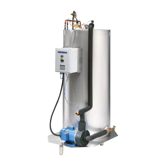
Page 16: Chiller Assembly, Model Pmc 40/50
˝ Diameter Holes 24˝ 18˝ 12˝ 6˝ 1˝ See Detail C ELEVATION VIEW DETAIL D CR0006 Mueller Bakery Chiller, Models PMC 40/50 and PMC 70/120 Effective February 23, 1999 Installation and Operation Manual, Part No. 9842311 Revised October 17, 2019... -
Page 17: Chiller Assembly Parts List, Model Pmc 40/50
Thermocouple, Sensor, Type “T” 9844400 Valve, Expansion 9844344 Leg, Assembly 9843187 Regulator Flow .75", 10 gpm Mueller Bakery Chiller, Models PMC 40/50 and PMC 70/120 Effective February 23, 1999 Installation and Operation Manual, Part No. 9842311 Revised October 17, 2019... -
Page 18: Chiller Assembly, Model Pmc 70/120
˝ Diameter Holes See Detail E 12˝ 9˝ 6˝ 3˝ 1˝ ELEVATION VIEW DETAIL D CR0007 Mueller Bakery Chiller, Models PMC 40/50 and PMC 70/120 Effective February 23, 1999 Installation and Operation Manual, Part No. 9842311 Revised October 17, 2019... -
Page 19: Chiller Assembly Parts List, Model Pmc 70/120
Thermocouple, Sensor, Type “T” 9844291 Valve, Expansion 9844344 Leg, Assembly 30478 Distributor 9843187 Regulator Flow .75", 10 gpm Mueller Bakery Chiller, Models PMC 40/50 and PMC 70/120 Effective February 23, 1999 Installation and Operation Manual, Part No. 9842311 Revised October 17, 2019... -
Page 20: Specifications/Electrical Data For Model Pmc 40/50 With 2 Hp Unit
Maximum Maximum Model No. Ampere Fuse Ampere Fuse OESE-A351 27.4 — — OESE-A353 — — 19.3 Mueller Bakery Chiller, Models PMC 40/50 and PMC 70/120 Effective February 23, 1999 Installation and Operation Manual, Part No. 9842311 Revised October 17, 2019... -
Page 21: Refrigeration Cycle Diagram
CR0010 EPA REFRIGERANT REGULATIONS* The Mueller bakery chiller system is designed to operate with R-507, a Class II HFC refrigerant. R-507 refrigerant is an HFC binary mixture of 50% R-125 (pentafluoroethane) and 50% R-143a (1, 1, 1-trifluoroethane). R-507 refrigerant is specified by ASHRAE Standard 34 Safety Classification as an “A-1” refrigerant with low flame propagation and low toxicity. -
Page 22: Thermal Expansion Valve (Tev) Superheat Adjustment
IMPORTANT: Damage to the compressor may occur if the liquid refrigerant reaches the compressor. Check the superheat setting and make final adjustments at a product temperature near the setpoint for the best performance. Mueller Bakery Chiller, Models PMC 40/50 and PMC 70/120 Effective February 23, 1999 Installation and Operation Manual, Part No. 9842311... -
Page 23: Thermal Expansion Valve Superheat Adjustment Diagram
Suction Gauge Thermostatic Expansion Valve Suction Line Liquid Line Service Valve Service Valve Bakery Chiller CR0011 Mueller Bakery Chiller, Models PMC 40/50 and PMC 70/120 Effective February 23, 1999 Installation and Operation Manual, Part No. 9842311 Revised October 17, 2019... -
Page 24: Label No. 8826319, Etl
SERIAL NUMBER VOLTS HERTZ PHASE DESIGN PRESSURE DESIGN PRESSURE LOW SIDE HIGH SIDE COOLING MEDIA MISCELLANEOUS Mueller Bakery Chiller, Models PMC 40/50 and PMC 70/120 Effective February 23, 1999 Installation and Operation Manual, Part No. 9842311 Revised October 17, 2019... -
Page 25: Label No. 8820677, Ground Symbol
9908 8823374 LABEL NO. 9901403, IN 9901403 LABEL NO. 9901404, OUT 9901403 9901404 9901404 Mueller Bakery Chiller, Models PMC 40/50 and PMC 70/120 Effective February 23, 1999 Installation and Operation Manual, Part No. 9842311 Revised October 17, 2019... -
Page 26: Section 9.0 - Warranty
ONE-YEAR PARTS WARRANTY Paul Mueller Company (hereafter referred to as Company) will repair or (at the Company’s option) replace any part or portion of a Mueller® bakery chiller found to be defective in workmanship or material under normal use, service, and installation procedures, for a period of one (1) year from the date of installation by the original purchaser-user, or eighteen (18) months from the date of shipment from the Company’s factory, whichever occurs first. -
Page 27: Section 10.0 - Installation And Service Notes
Telephone: Telephone: Email: Email: Chiller Model: Serial No.: Compressor Model: Serial No.: Date of Installation: Notes: Mueller Bakery Chiller, Models PMC 40/50 and PMC 70/120 Effective February 23, 1999 Installation and Operation Manual, Part No. 9842311 Revised October 17, 2019... - Page 30 1600 West Phelps Street | Springfield, Missouri 65802, U.S.A. Service: 1-800-756-5991 | DFETechService@paulmueller.com 1-800-MUELLER | WWW.PAULMUELLER.COM ©2019 Paul Mueller Company | 9842311...
Need help?
Do you have a question about the PMC 40/50 and is the answer not in the manual?
Questions and answers