Table of Contents
Advertisement
Quick Links
Advertisement
Table of Contents

Related Manuals for Keysight Technologies N2791A


Summary of Contents for Keysight Technologies N2791A
- Page 1 N2791A 25 MHz and N2891A 70 MHz High-Voltage Differential Probes User Guide...
- Page 2 WRITTEN AGREEMENT WITH WARRANTY beyond those set forth in the EULA shall TERMS COVERING THE MATERIAL IN THIS apply, except to the extent that those DOCUMENT THAT CONFLICT WITH THESE terms, rights, or licenses are explicitly Keysight N2791A/N2891A High-Voltage Differential Probes User Guide...
-
Page 3: Table Of Contents
N2891A Plots Using the Accessories Safety Hook and Alligator Clips Safety Hook and High-Voltage Alligator Clips Extreme Temperature Probing Kit N2791A Performance Verification Procedures DC Differential Gain Accuracy Bandwidth N2791A Performance Verification Test Record Keysight N2791A/N2891A High-Voltage Differential Probes User Guide... - Page 4 Contents N2891A Performance Verification Procedures DC Differential Gain Accuracy Bandwidth N2891A Performance Verification Test Record Offset Zero Calibration Procedure Keysight N2791A/N2891A High-Voltage Differential Probes User Guide...
-
Page 5: Inspecting, Cleaning, And Handling The Probe
Technologies Sales Office. If the shipping container is damaged, or the cushioning materials show signs of stress, notify the carrier as well as your Keysight Technologies Sales Office. Keep the shipping materials for the carrier’s inspection. The Keysight Technologies office will arrange for repair or replacement at Keysight Technologies’... -
Page 6: N2791A/N2891A High-Voltage Differential Probes
The N2791A/N2891A high-voltage differential probes allow conventional earth-grounded oscilloscopes to be used for floating signal measurements (up to 700 V of differential or common mode voltage for the N2791A and up to 7000 V of differential or common mode voltage for the N2891A). The... -
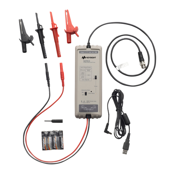
Page 7: Contents And Accessory Kits
Contents and Accessory Kits Contents and Accessory Kits Supplied Accessories The following table lists the parts included with the N2791A high-voltage differential probe. Part Quantity N2791A 25 MHz Differential Probe Safety Hook, Red Safety Hook, Black Alligator Clip, Red Alligator Clip, Black... - Page 8 For N2891A replacement accessories, you can order the N2891-68700 Differential Probe Accessory Kit. It includes: Part Quantity Safety Hook, Red Safety Hook, Black High Voltage Alligator Clip, Red High Voltage Alligator Clip, Black USB Power Cord (2 m) Keysight N2791A/N2891A High-Voltage Differential Probes User Guide...
-
Page 9: Optional Accessories
N2891A probes. The quantity for each accessory in the kit is the same as listed in Table Figure 1 N2791A Optional Accessories (Extreme Temperature Probing Kit) Table 1 N2791A Optional Accessories Accessory Extreme Temperature Hook Tip Adapters (Black) -
Page 10: Characteristics
Characteristics Characteristics Characteristics for the N2791A and N2891A high-voltage differential probes are shown below. The probe / oscilloscope should be warmed up for at least 20 minutes before any testing and the environmental conditions should not exceed the probe’s specified limits. - Page 11 202 mm x 83 mm x 38 mm (6.7 inches x 2.5 inches x 0.83 inches) (8.0 inches x 3.3 inches x 1.5 inches) Table 4 Environmental Specifications (same for both N2791A and N2891A) Description Specifications Temperature Operating: +5 °C to +40 °C (Probe without the N7013/14A extreme temperature probing kit) Operating: –40 °C to +85 °C (Probe with the N7013/14A extreme temperature probing kit)
-
Page 12: Safety Information
Do not attempt internal service or adjustment. WARNING Service should be carried out by a Keysight Technologies authorized service personnel. For any service needs, contact Keysight Technologies. Do not install substitute parts or perform any unauthorized modification WARNING to the instrument. -
Page 13: Safety Symbols
Observe Maximum Working Voltage. To avoid injury, do not use the WARNING N2791A probe above 1000 Vrms CAT III (both 10:1 and 100:1 attenuation settings) between each input lead and earth or between the two input leads. Do not use the N2891A probe above 5000 Vrms mains isolated (1000:1 attenuation) or 500 Vrms mains isolated (100:1 attenuation) between the two input leads. - Page 14 CAUTION sensitive parts and, therefore, you should be careful not to damage them through excessive bending or pulling. Avoid any mechanical shocks to this product in order to guarantee accurate performance and protection. Keysight N2791A/N2891A High-Voltage Differential Probes User Guide...
-
Page 15: Using The N2791A High-Voltage Differential Probe
This probe is to carry out differential measurements between two points CAUTION on the circuit under test. This probe is not for electrically insulating the circuit under test and the measuring instrument. Keysight N2791A/N2891A High-Voltage Differential Probes User Guide... -
Page 16: Using The N2891A High-Voltage Differential Probe
This probe is to carry out differential measurements between two points CAUTION on the circuit under test. This probe is not for electrically insulating the circuit under test and the measuring instrument. Keysight N2791A/N2891A High-Voltage Differential Probes User Guide... -
Page 17: N2791A Plots
(17 ns 10-90% Signal rise time) -0.2 -100 Time (ns) Figure 3 Graph of normalized step response (50Ω, 17 ns rising edge step genera- tor), 17 ns normalized rising edge (10-90%), 100:1 attenuation Keysight N2791A/N2891A High-Voltage Differential Probes User Guide... - Page 18 Graph of dB(Vin), dB(Vout) + 20dB, and dB(Vout/Vin) + 20dB frequency re- sponse, 10:1 attenuation Vout/Vin -2.5 Vout -7.5 Frequency (MH z) Figure 5 Graph of dB(Vin), dB(Vout) + 40dB, and dB(Vout/Vin) + 40dB frequency re- sponse, 100:1 attenuation Keysight N2791A/N2891A High-Voltage Differential Probes User Guide...
- Page 19 Figure 6 Graph of dB (Vout/Vin) + 20dB frequency response when inputs driven in common mode (common mode rejection), 10:1 attenuation Figure 7 Magnitude plot of probe input impedance versus frequency (differential & single-ended) Keysight N2791A/N2891A High-Voltage Differential Probes User Guide...
- Page 20 N2791A Plots 1100 V rm s Frequency (H z) Figure 8 Typical derating plot of the absolute maximum input voltage in common mode Keysight N2791A/N2891A High-Voltage Differential Probes User Guide...
-
Page 21: N2891A Plots
Probe Step Response (10 ns 10-90% rise time) -0.2 Time (nS) Figure 10 Graph of normalized step response (50 Ω, 10 ns rising edge step genera- tor), 10 ns normalized rising edge (10-90%), 1000:1 attenuation Keysight N2791A/N2891A High-Voltage Differential Probes User Guide... - Page 22 N2891A Plots Frequency Hz Figure 11 Graph of dB (S21) + 40 dB frequency response, 100:1 attenuation Frequency Hz Figure 12 Graph of dB (S21) + 60 dB frequency response, 1000:1 attenuation Keysight N2791A/N2891A High-Voltage Differential Probes User Guide...
- Page 23 Figure 13 Graph of dB (S21) + 40 dB frequency response when inputs driven in com- mon mode (common mode rejection), 100:1 attenuation Figure 14 Magnitude plot of probe input impedance versus frequency, single-ended Keysight N2791A/N2891A High-Voltage Differential Probes User Guide...
- Page 24 N2891A Plots and differential Vrms Frequency (Hz) Figure 15 Typical derating plot of absolute maximum input voltage in common mode Figure 16 Input impedance equivalent circuit diagram Keysight N2791A/N2891A High-Voltage Differential Probes User Guide...
-
Page 25: Using The Accessories
Using the Accessories Using the Accessories The accessories supplied with the N2791A and N2891A probes are attached by pushing them onto the probe leads as shown below. probe lead hook or clip The following accessories are supplied with the N2791A probe. -
Page 26: Extreme Temperature Probing Kit
Extreme Temperature Probing Kit For extreme temperature probing, you can connect the N7013/14A extreme temperature probing kit to the N2791A probe. The N7013/14A extreme temperature probing kit is not compatible with the N2891A probe. The N7013/14A extreme temperature probing kit is not supplied with the NOTE probe. - Page 27 Connecting the Extreme Temperature Differential Extension Cables Connect the red and black extreme temperature hook tip adapters to the extreme temperature differential extension cables which are already connected to the existing probe cables. Keysight N2791A/N2891A High-Voltage Differential Probes User Guide...
- Page 28 Connect the red and black extreme temperature banana-to-socketed tip adapters to the extreme temperature differential extension cables which are already connected to the existing probe cables. Figure 19 Connecting the Extreme Temperature Banana-to-Socketed Tip Adapters Keysight N2791A/N2891A High-Voltage Differential Probes User Guide...
-
Page 29: N2791A Performance Verification Procedures
N2791A Performance Verification Procedures The following procedure can be used to test the DC differential gain accuracy and bandwidth of the N2791A differential probe. Please note that these procedures do not indicate that these characteristics are warranted. Instead, these procedures are meant to give you an idea of how your probe performs. -
Page 30: Bandwidth
N2791A Performance Verification Procedures Connect the output of the N2791A probe to channel 1 of the oscilloscope. Attach the BNC adapter to the Fluke channel 1 active head. Attach the differential probe input leads by clipping the alligator clamp to the BNC adapter banana post. -
Page 31: N2791A Performance Verification Test Record
Certification Temperature:_____________________ Test Probe Settings Limits Results Gain 100:1 98 mV to 102 mV Gain 10:1 98 mV to 102 mV Bandwidth 10:1 Greater than or equal to 210 mV - scope vertical accuracy Keysight N2791A/N2891A High-Voltage Differential Probes User Guide... -
Page 32: N2891A Performance Verification Procedures
N2891A probe. Because this adapter has exposed metal surfaces, only qualified personnel should perform any testing with voltage levels exceeding 30 Vrms. All pertinent safety rules and guidelines for elevated voltage measurements should be followed and adhered to. Keysight N2791A/N2891A High-Voltage Differential Probes User Guide... - Page 33 14 Record the DC amplitude of the square wave and divide 10 into just the amplitude of the oscilloscope. Verify that the probe gain accuracy is ±2% + scope gain accuracy. 15 Disable the calibrator output and leave the setup connected for the next procedure. Keysight N2791A/N2891A High-Voltage Differential Probes User Guide...
-
Page 34: Bandwidth
70 MHz, 50 Ω load. Write down the peak-to-peak amplitude measured by the oscilloscope. It should be greater than or equal to 35 mV - scope vertical accuracy. Disable the generator output and disconnect the probe input. Keysight N2791A/N2891A High-Voltage Differential Probes User Guide... -
Page 35: N2891A Performance Verification Test Record
Certification Temperature:_____________________ Test Probe Settings Limits Results Gain 100:1 98 mV to 102 mV Gain 1000:1 98 mV to 102 mV Bandwidth 10:1 Greater than or equal to 35 mV - scope vertical accuracy Keysight N2791A/N2891A High-Voltage Differential Probes User Guide... -
Page 36: Offset Zero Calibration Procedure
Press [Default Setup] and [Auto Scale] on the oscilloscope. Press the channel 1 button, then press the Probe softkey, and then set the units to Volt and the probe attenuation to 10:1 (for N2791A) or 100:1 (for N2891A). Set the scope to DC coupled mode and the scope offset to 0 Volt. - Page 37 Keysight N2791A/N2891A High-Voltage Differential Probes User Guide...
- Page 38 This information is subject to change without notice. © Keysight Technologies 2018 N2791-97008, December 2018 www.keysight.com...