Advertisement
Quick Links
WARNINGS AND CAUTIONS:
• TO AVOID FIRE, SHOCK, OR DEATH; TURN OFF POWER AT CIRCUIT BREAKER OR FUSE AND TEST THAT
POWER IS OFF BEFORE WIRING!
• To be installed and/or used in accordance with appropriate electrical codes and regulations.
• If you are unsure about any part of these instructions, consult an electrician.
• Sensors must be mounted on a vibration free surface.
• Do not terminate using data type wire, such as Cat 5/5E.
• All sensors must be mounted at least 6 feet away from air vents, air handlers, and reflective surfaces (windows/mirrors).
• Do not touch the surface of the lens. Clean outer surface with a damp cloth only.
Tools needed to install your Sensor
Slotted/Phillips
Screwdriver
Electrical Tape
Pliers
Pencil
Cutters
Parts Included List
Sensor (1)
Threaded Rod (1) and Hex Nut (1)
#8-32 x 1/2" Screw (2)
Half Mask (1)
#8-32 x 1-1/2" Screw (2)
360° Perforated Mask (1)
#8-32 Washer and Nut (2)
Plastic Washer (1)
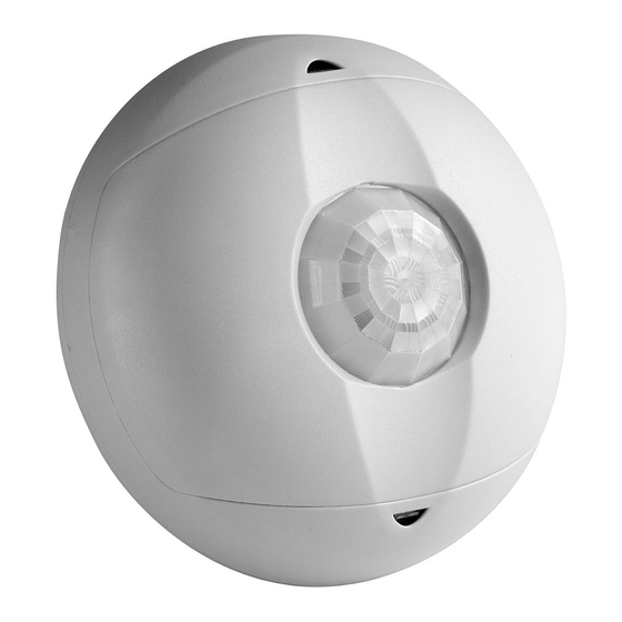
DESCRIPTION
The Occupancy Sensor is a low-voltage infrared sensor that works with the OSPxx
Series and CN100 power pack, or other Class 2 power supplies, to automatically
control lighting. The sensor turns the lights on and keeps them on whenever occupancy
is detected and will turn them off after the 'delayed-off time' has expired.
The sensor continually analyzes and adjusts to changing conditions. The sensor uses
the latest microprocessor-based technology which permits it to continually adjust and
optimize its performance.
Infrared motion detection gives higher false triggering immunity that yields a sensor
with excellent performance.
INSTALLING YOUR OCCUPANCY SENSOR
NOTE: Use check boxes
when Steps are completed.
WARNING:
TO AVOID FIRE, SHOCK, OR DEATH; TURN OFF
Step 1
POWER at circuit breaker or fuse and test that power is off before wiring!
OFF
ON
OFF
ON
OFF
ON
OFF
ON
OFF
ON
OFF
ON
OFF
ON
OFF
ON
OFF
ON
OFF
ON
OFF
ON
OFF
ON
Preparing and connecting wires:
Step 2
Strip Gage
1/2"
(measure bare
(1.3 cm)
wire here)
Cut
(if necessary)
Typical Installations:
Step 3
Listed are 3 typical installation options (A, B, and C). Choose one that
best suits your needs. Other methods of installation may be possible but
they have not been described here.
A. Drop Ceiling Installation (Mounting Option A):
NOTE: Use the threaded rod included.
1. Select location for mounting of sensor and proper masking for your application
(refer to Mounting Location Diagram).
2. Use the supplied threaded rod or other methods to make a hole (1/2" to 1") in the ceiling
tile just large enough to pass the body of the threaded rod through.
3. Insert the sensor wires through the flared end of the threaded rod. Position the threaded
rod to the base of the sensor.
4. Insert the flared end of the threaded rod into the opening in the bottom of the sensor
and twist to lock into place.
Infrared Ceiling Mounted Occupancy Sensor
Cat. No. OSCØ4-R and OSC15-R
To be used with 24VAC/VDC OSPxx Series and CN100 Power Pack or other Class 2 power supplies
INSTALLATION INSTRUCTIONS
Voltage Range
Cat. No.
Description
High
OSC04-RIW
15-28VAC/VDC
Density
Extended
OSC15-RIW
15-28VAC/VDC
Range
Step 3 cont'd
5. Push the wires into the hole in the ceiling tile and insert the threaded rod until the
sensor is flush with the tile.
6. Insert wires through the hole in the included washer, then place the included washer
over the rod and screw on the included hex nut.
7. Class 2 Wiring: Connect low-Voltage wires from Power Pack to Sensor per WIRING
DIAGRAM as follows: Twist strands of each lead tightly and, with circuit conductors,
push firmly into appropriate wire connector. Screw connectors on clockwise making
sure that no bare conductor shows below the wire connectors. Secure each connector
with electrical tape.
8. Rotate the sensor to the desired orientation. Note that the sensor base and back cover
are keyed. To lock the device in place, ensure that the arrows are not aligned.
9. Restore power at circuit breaker or fuse to Power Pack. INSTALLATION IS
COMPLETE. NOTE: All wired connections to the sensor are Class 2 low voltage.
Mounting Option Diagram A
Occupancy Sensor Mounted to Drop Ceiling Using Threaded Rod
Low-Voltage Wires
Drop Ceiling
1" thick maximum
Nut
Washer
Threaded Rod
NOTE: Wires threaded through
the Threaded Rod
B. Wallboard or Drop Ceiling Installation (Mounting Option B):
NOTE: You may use the mounting screws, nuts and washers included, or screws in
combination with commercially available wall anchors.
1. Select location for mounting of sensor and proper masking for your application
(refer to Mounting Location Diagram).
2. Make a hole in the ceiling tile or wallboard large enough to pass the wire connections
and wire nuts through (approximately 1" diameter).
3. Remove the back cover of the sensor. Hold the back cover and body of the sensor and
rotate until the two arrows line up and pull apart.
4. Install back cover of the ceiling sensor to the wallboard or drop ceiling using the
included screws, nuts and washers, or screws in combination with commercially
available wall anchors.
5. Class 2 Wiring: Connect low-Voltage wires from Power Pack to Sensor per WIRING
DIAGRAM as follows: Twist strands of each lead tightly and, with circuit conductors,
push firmly into appropriate wire connector. Screw connectors on clockwise making
sure that no bare conductor shows below the wire connectors. Secure each connector
with electrical tape.
6. Push wire connections through the center hole of the back cover and into the ceiling.
7. Secure the sensor body to the back cover by aligning the arrows. Lock it by turning the
sensor such that the arrows do not line up.
8. Rotate the sensor to the desired orientation.
9. Restore power at circuit breaker or fuse to Power Pack.
INSTALLATION IS COMPLETE.
Mounting Option Diagram B
Occupancy Sensor Mounted to Wallboard or Drop Ceiling Using Screws
Low-Voltage Wires
Low-Voltage Wires
Nut (2 places)
Washer (2 places)
Wallboard
Sensor Back
Ceiling
Cover
Mounting
Wallboard Ceiling
Screws
(2 places)
Keylock Arrow
Sensor Base
Back Cover shown mounted
Sensor Front Cover
on ceiling with screws
CATALOG ITEMS
Current
Suggested
Consumption
Mounting Location
HVAC Relay
Coverage
Mount in center of
Isolated Relay
15mA DC, 30mA AC
450 sq. ft.
room/area, 8-10ft height
1A @ 30VAC/VDC
Isolated Relay
Mount in center of
15mA DC, 30mA AC
1500 sq. ft.
1A @ 30VAC/VDC
room/area, 8-10ft height
Step 3 cont'd
C. Junction Box or Surface Mount Raceway Installation
(refer to Mounting Diagrams):
NOTE: Listed below are suggested JUNCTION BOX installation applications which
require mounting to conduit in one of the following three ways:
Occupancy Sensor Mounted to Octagon
Box Installed Flush to Wallboard Ceiling
Octagon Box
4" x 1-1/2" deep
Low-Voltage
Wires
#8-32 Screws
(2 places)
Wallboard or
Drop Ceiling
TABLE 2: WIRE DESIGNATIONS
Name
Color
Gage
Temp/Voltage
Power (24 VAC/VDC)
Red
24
200° C/ 600V
Common
Black
24
200° C/ 600V
Occupancy
Blue
24
200° C/ 600V
Relay
Brown (N/C)
24
200° C/ 600V
Brown/White (N/O)
24
200° C/ 600V
Green (Common)
24
200° C/ 600V
Hot (Black)
Back Cover open center to
route Low-Voltage Wires
Line
120-277-347 VAC
Mounting Screw
60Hz
Back Cover internal
surface shown
Neutral (White)
FCC COMPLIANCE STATEMENT:
This device complies with part 15 of the FCC rules. Operation is subject to the following two conditions:
(1) This device must not cause harmful interference, and (2) This device must accept any interference
received, including interference that may cause undesired operation. Any changes or modifications not
expressly approved by Leviton could void the user's authority to operate this equipment.
Step 3 cont'd
Occupancy Sensor Mounted to Round Fixture
with Raceway for Wallboard Installation
Wire Mold Back Cover
Wire Mold Round Fixture
Box Cat. No. V5738
(for raceway mount)
Mounting Screws
(4 places)
Wallboard Ceiling
Wire Mold Raceway
(use applicable fittings)
Wiring Diagram: Multiple Sensor, Single Power Pack
OSPxx Series
Power Pack
Sensor
Red
Black
Red
To BAS
Blue
System
(Control)
Black
N/C - Brown
Common-Green
Blue
N/O-Brown/White
Red
To BAS
Blue
System
Black
Blue
N/C - Brown
Common-Green
Blue
Black
N/O-Brown/White
White
PK-93733-10-00-0A
Back Cover Screws
(4 places)
Low-Voltage Wires
Black
NOTE: Ensure to
cap wires that are
not being used.
Load
White
Advertisement

Subscribe to Our Youtube Channel
Related Manuals for Leviton OSC04-R Series


Summary of Contents for Leviton OSC04-R Series
- Page 1 8-10ft height • Do not touch the surface of the lens. Clean outer surface with a damp cloth only. expressly approved by Leviton could void the user's authority to operate this equipment. Tools needed to install your Sensor Step 3 cont'd...
- Page 2 Leviton Manufacturing Co., Inc., Att: Quality Assurance Department, 201 North Service Road, Melville, New York 11747. This warranty excludes and there is disclaimed liability for labor for removal of this product or reinstallation.
Need help?
Do you have a question about the OSC04-R Series and is the answer not in the manual?
Questions and answers