Table of Contents
Advertisement
Advertisement
Table of Contents
Troubleshooting

Related Manuals for RR Mechatronics Interrliner Series


Summary of Contents for RR Mechatronics Interrliner Series
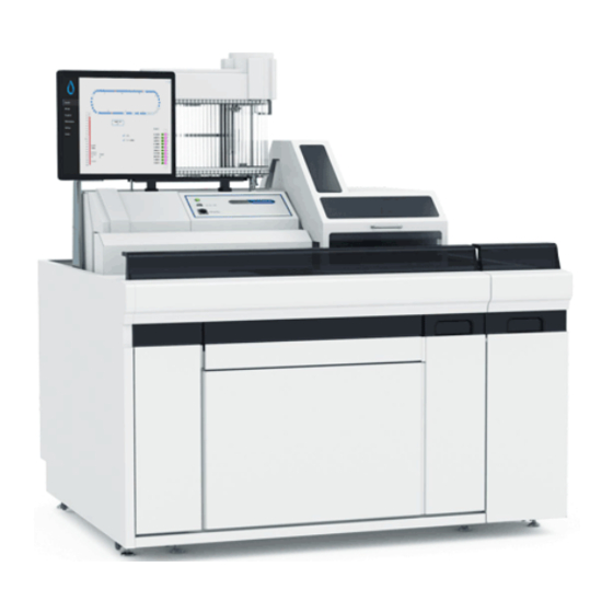
- Page 1 Installation manual Interrliner MRN-023-EN Version 8.20...
-
Page 3: Table Of Contents
Contents Contents - Application..............- Copyright. - Page 4 Contents 4.1.2.1 - - Unpacking instructions Start-Pool and End-Pool XN..... . 4.1.2.2 - - Unpacking instructions analyser section......4.1.2.3 - - Connecting the parts.
- Page 5 Contents 4.2.6.7 - - Set room temperature......... . 4.2.6.8 - - First fill and clean.
- Page 6 Contents 5.34 - - Menu M34 M31 (3) Short belt motor (Front return line) ......5.35 - - Menu M35 By-pass ESR Unit.
- Page 7 Contents 9.1 - - EHST080933 PCB Elevator board......... 9.2 - - EHST080951 PCB Multi I/O (Start-Pool, v2) .
-
Page 8: Application
Application Application This manual, MRN-023, is applicable for the following instrument models: Interrliner XN1 with output EHST109421 Interrliner XN2 with output EHST109422 Interrliner XN3 with output EHST109423 Referred as "Interrliner XN" Interrliner XN1 FRL EHST109621 Interrliner XN2 FRL EHST109622 Interrliner XN3 FRL EHST109623 Referred as "Interrliner XN FRL"... -
Page 9: Copyright
1620 AE Hoorn The Netherlands De Corantijn 13 Office address: 1689 AN Zwaag The Netherlands © Copyright RR Mechatronics Manufacturing B.V. All rights reserved. Subject to changes without prior notice. Issued by the Support Department of RR Mechatronics MRN-023-EN Version 8.20 Interrliner... -
Page 10: Document History Overview
Document history overview Document history overview MRN-023-EN Published date 04-2020 Issue No Date Revised Section(s) Changes Authorised ▪ New bottle for deionized water 8.20 April. 2020 Reagent installation H. Schavemaker ▪ Default speed rack motor changed Appendix ▪ Minor editorial text changes ▪... - Page 11 Document history overview ▪ Corrected the menu structure 5.00 October 2004 H.E. van Dijk ▪ Changed the PCDPS in Lab Comm. 4.00 September 2003 H.E. van Dijk ▪ Update the screen pictures in 3.00 January 2003 Section 5 H.E. van Dijk section 5 ▪...
-
Page 12: Instrument Description
Instrument description Instrument description The Interrliner consists of the following main modules: Start-pool ▪ Loading of racks through belt-driven transport system ▪ Capability of holding 21 Sysmex racks ▪ Keyboard (in drawer) Interrliner XN: Printer stand ▪ Tube handling and transport ▪... - Page 13 Instrument description ▪ ESR measuring instrument with a belt holding 84 precision's bore glass Westergren pipettes. ▪ Automated aspiration of the sample tube. ▪ Automated dilution of EDTA blood sample with citrate. ▪ Automated measurement of ESR after 30 or 60 minutes. ▪...
-
Page 14: Technical Specifications Interrliner
Instrument description 1.1 - Technical specifications Interrliner Westergren method ESR method ICSH J. M. Jou; Int. Journal of Laboratory Hematology 2011; 33: 125-132 CLSI Procedures for the Erythrocyte Sedimentation Rate Test; Approved Standard- Fifth Edition H02-A5, Vol. 31 No. 11; 2011 Temperature compensation R.W. - Page 15 Instrument description 115/230VAC, 50/60 Hz Mains voltage Per ESR Unit Slow blow 230V 2.5 Amp / 115V 5 Amp Fuse (20 x 5 mm) Transport Unit Slow blow 230V 1.6 Amp / 115V 3.15 Amp Standby 90 VA 2x90VA 3x90VA Power consumption Maximum 650 VA...
-
Page 16: Accessories Kit
Instrument description 1.2 - Accessories kit The Interrliner comes with an accessories kit. For a complete list of the the contents of accessories kit, see Appendix - Article reference list Interrliner 1.3 - Sample unit The analyser section is located in the center part of the Interrliner, the following three units: 1. -
Page 17: Indexer
Instrument description 1.4 - Indexer ** CAUTION MOVING PARTS ** The Indexer is a carriage that holds the rack and moves independently from the conveyor belt. The rack is being checked for the presence of sample tubes and the barcode is being read. If the barcode can not be read right away, a spring assisted tube rotator is pushed onto the tubes and turns the sample tubes at the barcode reader position clock-wise and anti-clockwise until the barcode reader reads a positive patient ID. - Page 18 Instrument description ATTENTION: The quality of the barcode labels is of critical importance for the correct function of the sample robot. Labels may not come loose or have “dog-ears”! Poor label quality cannot be compensated by mechanical adjustments! MRN-023-EN Version 8.20 Interrliner...
-
Page 19: General Safety Information
Instrument description 1.5 - General safety information The instrument described in this manual is designed to be used by properly trained personnel only. For the correct and safe use of this instrument it is essential that both operating and servicing personnel follow generally accepted safety procedures in addition to the safety precautions specified in this manual. -
Page 20: Type Plate Interrliner
Instrument description Warning sign to prevent personal injury due to hot surfaces. Warning sign to prevent personal injury due to electrical shocks. General warning. General note. This symbol indicates a reference to this or other product documentation 1.6 - Type plate Interrliner The type plate of the complete instrument is located at the inner side of the power box and is visible with the drawer pulled out. -
Page 21: Standard Operating Procedures (S.o.p.)
Standard Operating Procedures (S.O.P.) Standard Operating Procedures (S.O.P.) In this section the following issues can be found: ▪ Basics of Bio safety ▪ S.O.P. for working with bio hazardous materials ▪ Safety warning ▪ E.C. Declaration ▪ Labels and stickers on containers 2.1 - Basics of bio safety Basic rules on bio safety in a laboratory;... -
Page 22: Medical Requirements
Standard Operating Procedures (S.O.P.) The "normal" research activities carried out in a blood laboratory expose workers to human blood, urine, sweat, semen, saliva and muscle tissue. For the purpose of assessing risk, we assume that all volunteers to our clinical studies are not normal healthy individuals, and take appropriate precautions. - Page 23 Standard Operating Procedures (S.O.P.) Laboratory access: Access to the haematology laboratory is limited to persons who are directly involved with the testing equipment. Children are not permitted in the laboratory. Personal protective equipment: Laboratory and maintenance personnel are expected to use a laboratory coat while working in the blood laboratory.
-
Page 24: Stickers Of The Reagents Containers
Standard Operating Procedures (S.O.P.) 2.3 - Stickers of the reagents containers MRN-023-EN Version 8.20 Interrliner... -
Page 25: Pre-Installation Requirements Interrliner
Pre-installation requirements Interrliner Pre-installation requirements Interrliner In order to install the Interrliner-system and integrate it with the Sysmex HST - XN system, the following preparations need to be carried out: 3.1 - From the office ▪ Distributor needs to send a sample of the tubes and bar codes which will be used to ensure correct testing of the instrument and of the tube handling of the robotic arm. -
Page 26: From The Location
Pre-installation requirements Interrliner 3.2 - From the location ▪ Distributor needs to check the installation area for available floor space and appropriate passageways (See Appendix - Interrliner floor overall dimensions ▪ Minimum doorway size is 630 millimeters. ▪ The installation area must comply with the following: ▪... -
Page 27: Installation
Installation Installation 4.1 - Installation of Interrliner: phase one The installation of the Interrliner should only be carried out by trained service personnel. Before unpacking the Interrliner, we recommend that the packing should be checked for damage. (Triggered tip and tells/"shock and tell".). Any damage must be reported to the distributor. Before the actual installation of the Interrliner the Integration into the Sysmex system need to be carried... -
Page 28: Unpacking Instructions Start-Pool And End-Pool Xn
Installation Remove all binding, cardboard boxes and all the support straps, from the pallets. 4.1.2.1 - Unpacking instructions Start-Pool and End-Pool XN Start with removing the Start-Pool and Remove first the two transport brackets from the End- End-Pool from the pallet. Pool and lift the unit from the pallet. -
Page 29: Unpacking Instructions Analyser Section
Installation Remove the two transport brackets from the Start-Pool and lift the unit from the pallet. 4.1.2.2 - Unpacking instructions analyser section MRN-023-EN Version 8.20 Interrliner... - Page 30 Installation Remove the two transport brackets (1) from the left side of the analyser section and loosen the two transport brackets from the right side. Remove all foam blocks. Remove three bolts (2) which hold the wooden beam onto the pallet. Pull (3) the beam from under the pallet.
-
Page 31: Connecting The Parts
Installation Remove the other tiewraps as indicated. 4.1.2.3 - Connecting the parts Move all the parts to the intended location in the lab. Use the bolts and nuts to connect the main parts. They are send in a plastic bag, attached at the back of the instrument. -
Page 32: Unpacking Interrliner(Single System Interrliner Xn Frl)
Installation Reconnect the power, communication and sensor cables at the front of the units to the neighborly units. See Appendix - PCB Internal connections 4.1.3 - Unpacking Interrliner(single system Interrliner XN FRL) The whole system is packed onto three pallets. ▪... -
Page 33: Unpacking Instructions Start-Pool (Single System Interrliner Xn Frl)
Installation Remove all binding, cardboard boxes and all the support straps, from the pallets. 4.1.3.1 - Unpacking instructions Start-Pool (single system Interrliner XN FRL) Applicable for Interrliner XN FRL Start with removing the Start-Pool and ESR analyser unit from the pallets. Remove the two transport brackets from the Start-Pool and lift the unit from the pallet. - Page 34 Installation Remove the two transport brackets (1) from the left side of the analyser section and loosen the two transport brackets from the right side. Remove all foam blocks. Remove three bolts (2) which hold the wooden beam onto the pallet. Pull (3) the beam from under the pallet.
-
Page 35: Connecting The Parts Interrliner Xn Frl
Installation Remove the other tiewraps as indicated. 4.1.3.3 - Connecting the parts Interrliner XN FRL 1. Move all the parts to the intended location in the lab. 2. Push the units together. Observe that the positioning blocks are placed in the appropriate grooves and that no cables are jammed between the units. -
Page 36: Unpacking Esr Analyser Unit System
Installation ▪ Remove the 2 lock plates EHST060720 at both sides. ▪ Lift the robotic unit from the support frame. ▪ Turn the support frame over to the side. ▪ Move both units to the work location. ▪ Replace the robotic unit on the support frame. ▪... - Page 37 Installation 1. Install the PC on the PC base plate as shown in the picture, with the connectors at the back and the on/off button at the front. 2. Press the PC on the Velcro. 3. Replace the top cover plate. Installing PC power supply 1.
- Page 38 Installation 9. COM2: Serial connection for LIMS 10. COM:1 Serial connection RS232 to IIC 11. HDMI monitor cable comes from the monitor 12. Power cable MRN-023-EN Version 8.20 Interrliner...
-
Page 39: Set-Up The System
Installation 4.1.7 - Set-up the system The Interrliner is now at the intended location. 4.1.7.1 - Setting up the rack handling system Attention: In order to align the Start-Pool to the Sysmex HST - XN, the entire instrument must be moved! Movement of the Start-Pool only will result in internal misalignment of the units and is not allowed! ▪... - Page 40 Installation ▪ Check forward / backward alignment: racks coming from Sysmex HST - XN should enter the feeder belt in the middle of the passageway. MRN-023-EN Version 8.20 Interrliner...
-
Page 41: Setting Up The Esr Analyser Unit
Installation 4.1.7.3 - Setting up the ESR analyser unit Unscrew the 3 adjustable legs to a neutral position in the middle before placing the ESR analyser unit to be able to adjust the level in a next stage. Check that the two vacuum pump transportation screws are removed. Pull the slide frame back and place the ESR analyser unit onto the frame. - Page 42 Installation ▪ The two communication cables are labeled with numbers (Needle board-Elevator board) and 509 Nozzle board-Indexer board). ▪ The power cable has two connectors that are labeled with number 406 Power supply Indexer and Elevator board). ▪ Connect the communication cable with label to the communication socket on the elevator board.
-
Page 43: Installation Of The Sensors
Installation ▪ Connect the power lead to the distribution box of the Interrliner. ▪ Open the cover on the left and install the two peristaltic pump tubes The thick silicon tube on the left peristaltic pump (Rinse) and the thin silicon tube on the right peristaltic pump (Saline). -
Page 44: Unpacking And Install The Monitor Parts
Installation 1. Guide the flat cable through one hole and connect this cable. 2. Guide all tubing from the top unit of the instrument via one of the holes at the back of the box. 3. Connect the tubing 1 by 1 onto the corresponding tube connectors on the inside of the box. 4. -
Page 45: Main Power Connection
Installation 1. Place the bracket about 4.5 cm from the beam. 2. Insert 3 pieces of plastic foam. 3. Insert 3 square nuts on top of the plastic foam. 4. Place the monitor bracket on the frame as shown in the picture. -
Page 46: Installation Of Support Units
Installation Next to a serial connection the Interrliner can be connected to a Host system with a TCP/IP interface. 4.1.7.7.2 - Connection to Sysmex HST - XN Connect the communication cables Interrliner EHST089134/EHST089135 or EHST089136. The Sysmex HST - XN can only recognize the instrument through a “power-on” cycle; both the Sysmex HST - XN and Interrliner must be switched OFF, first turn ON Interrliner and then the Sysmex HST - XN. -
Page 47: Barcode Interface
Installation Installation of the sensors , tubes, cables and labeling the sensors. Measure the needle depth Preparing the tube adapter (needle unit) Needle depth settings 4.1.8.1 - Barcode interface The barcode reader can be found on the analyser section of the Interrliner. There is no barcode reader in the ESR analyser unit itself. - Page 48 Installation The sensors and the reagents have the following color codes: Reagent Color code Starrsed Rinse solution Green Starrsed Saline Yellow Starrsed Diluent Grey Deionized water Blue Starrsed Disinfectant White 4.1.8.2.1 - Starrsed Rinse solution Starrsed Rinse solution is a dedicated IVD product, developed exclusively for automatic rinsing of the Westergren pipettes in Starrsed ESR analyzers.
-
Page 49: Waste Line Connection To Central Waste System
Installation If large cubitainers are used: Replace the Diluent cubitainer. 4.1.8.2.4 - Deionized water After each aspiration, the fill nozzle is flushed with de-ionized water. The water container is a 5-liter container and must be filled up when empty. Add one or two drops of Starrsed Saline to the deionized water to avoid <bottle empty alarm>. -
Page 50: Safety Stop Settings
Installation Setting 1 Setting 5 See also Needle depth settings for the correct setting of the safety stop. 4.1.8.5 - Safety stop settings Round bottom tubes Tube bottom shape Tube manufacturer and model Tube diameters Safety stop setting Round Various 10…16 mm Flat bottom tubes Tube bottom shape... -
Page 51: Measuring Maximum Safe Needle Depth
Installation 4.1.8.6 - Measuring maximum safe needle depth Measuring maximum safe needle depth: When the safety stop is set correctly, switch the instrument OFF and disconnect the flat cable from the tube motor (lower motor). Place an empty sample tube in the unit and push the outer needle down into the tube. -
Page 52: The Robot Unit Cover
Installation ▪ Switch the ESR analyser unit. ▪ Switch the PC and the monitor. ▪ Wait until "Windows" is ready for use. ▪ Start the Starrsed software. ▪ Observe the Robotic arm movement during the start-up, after finishing the reset sequence the ESR analyser unit is ready for use. -
Page 53: Alignment Of The Esr Analyser Unit To The Robotic Arm
Installation 1. Mount robot hood back on the frame 2. Adjust the mechanical key side-and/or downwards ▪ The adjustment front to back is used to get the Key in the look itself ▪ The adjustment up and down is used to get the robot cover correctly closed 3. -
Page 54: Extra Alignment Of The Esr Analyser Unit To The Robotic Arm
Installation Level the ESR analyser unit horizontally by adjusting the three variable feet and make sure the airbubble in the level gauge is in the middle of the black target ring. The alignment is already done in the factory but needs to be checked. Take a rack with a sample tube which will be used by the client. - Page 55 Installation The needle assembly can move in three directions. ▪ Up and down ▪ To the left and to the right ▪ To the front and to the back Note: The second up/down screw is at the other side of the needle assembly.
-
Page 56: Mount Backplates
Installation ▪ To the left and to the right If the above adjustment is not sufficient, the following adjustments on the location of the complete ESR unit can be done: 1. Adjustments for the front / back direction can be made with the 2 small setscrews in the slide blocks (located inside the groove). -
Page 57: Start-Up First Time
Installation 4.2.6 - Start-up first time Ensure that racks are correctly placed in the Interrliner; the groove on the side of the rack must catch the strip at the right side of the storage area. The Interrliner can store up to 21 racks. Each rack is fed in by the Sysmex HST - XN, trimmed and pushed automatically to the front where it lines up with the sampler conveyor-belt. -
Page 58: Limit Filter Settings
Installation 4.2.6.1.2 - 60 or 30 minute method As default the 60-minute method is used, Check which ESR method the ESR analyser unit unit must be set: the 60 minute method (default) or the 30 minute method. The 30 minute method setting is available at settings. -
Page 59: Set Room Temperature
Installation Example: Measure the safe needle depth. The sample probe depth is usually slightly less than the maximum safety distance, enter this depth in millimeters. This will be the depth that the sample probe goes down into the sample tube. ▪... - Page 60 Installation Start Fill and clean procedure: 1. Select button OK. 2. The needle goes down and the process is started. 3. When all the pipettes are filled, the needle goes back to the home position. 4. After the Fill & clean process is finished, a notification is given to stop the procedure. 5.
-
Page 61: Vacuum Flow Settings
Installation 4.2.6.9 - Vacuum flow settings The vacuum is adjusted on a standard vacuum flow, but should be set for the ideal average filling speed, due to local circumstances. Vacuum adjustment 1. Install the vacuum gauge at the T-junction between flow meter and the black orifice. 2. - Page 62 Installation MRN-023-EN Version 8.20 Interrliner...
-
Page 63: Starrsed Control Settings
Installation 4.2.7 - Starrsed Control settings If Starrsed Control will be used ,some settings have to performed. ▪ Check and set new "QC settings": ensure that "Send QC request to LIMS" and "Send QC result to LIMS" are set correctly according the labs preference. ▪... - Page 64 Installation (Check settings in Send start/stop character and Inspect check digit on/off) Action: Reprogram the barcode reader with the LAB barcode and CODE39. Display sample history screen or Display sample QC history ▪ Starrsed Control cannot be found in the screen.
-
Page 65: Keyboard Interrliner (Software V 4.Xx And Up) All Versions
Keyboard Interrliner (Software V 4.xx and up) All versions Keyboard Interrliner (Software V 4.xx and up) All versions The menu overview includes all available options of the software. The menu descriptions which are included are applicable for all Interrliner models. Interrliner XN: The keyboard for the transportation unit is located on top of the input-pool. - Page 66 Keyboard Interrliner (Software V 4.xx and up) All versions MRN-023-EN Version 8.20 Interrliner...
- Page 67 Keyboard Interrliner (Software V 4.xx and up) All versions MRN-023-EN Version 8.20 Interrliner...
-
Page 68: Navigation Through The Menus
Keyboard Interrliner (Software V 4.xx and up) All versions 5.1 - Navigation through the menus During normal operation, press "F1" key once to access the main menu M0.To access submenus and functions, press the item number shown at the front of the line. Press "ESC"... -
Page 69: Menu M0 Main Menu
Keyboard Interrliner (Software V 4.xx and up) All versions The submenus are listed by a menu number. (See overview in section Menu structure) The legend is; Line data or information in display Item is toggle function or input data Bold text is a default setting [ESC] is the key function 5.2 - Menu M0 Main menu... -
Page 70: Menu M4 M2 (1) General (Software V 4.Xx)
Keyboard Interrliner (Software V 4.xx and up) All versions 1. Send test data The test data string is similar to the normal out-put string of the ESR analyser unit, but the result is a dummy. Function is used to test Lab Comm communication. -
Page 71: Menu M6 M2 (3) Reset Unit
Keyboard Interrliner (Software V 4.xx and up) All versions 5.9 - Menu M6 M2 (3) Reset Unit Menu M6 (3) Reset unit See also the error handling 1. Start-Pool Reset the Start-Pool 2. End-Pool ** Reset the End-Pool 3. Conveyor belt Reset the Conveyor 4. - Page 72 Keyboard Interrliner (Software V 4.xx and up) All versions Menu M 11 (2) Slider motor (Start-Pool) 1. Time-out: 2 Time: 5 second 4 [ F2 ]=up [ F3 ]=down [ESC] [ ENT ] 2. Speed: 2 Speed: 220 4 [ F2 ]=up [ F3 ]=down [ESC] [ ENT ] 4.
-
Page 73: Menu M8 M5 (2) End-Pool
Keyboard Interrliner (Software V 4.xx and up) All versions 4. Test motor: Motor:on/off In0: 2 I: Motor current In1: 3 Err: In2: 4 [ F2 ]=on/off, [ESC] In0: Motor home In1: Motor limit In2: 5.11 - Menu M8 M5 (2) End-Pool Menu M8 M5 (2) End-Pool (only applicable for Interrliner XN) -
Page 74: Menu M8 M5 (2) (Xo Configuration)
Keyboard Interrliner (Software V 4.xx and up) All versions 4. Test motor: Motor:on/off In0: 2 I: Motor current In1: 3 Err: In2: 4 [ F2 ]=on/off, [ESC] In0: Home In1: In2: 5.12 - Menu M8 M5 (2) (XO configuration) Menu M8 M5 (2) End-Pool (only applicable for Interrliner XN) 1. - Page 75 Keyboard Interrliner (Software V 4.xx and up) All versions 2. Speed: 4 [ F2 ]=up [ F3 ]=down [ESC] 2 Speed: 220 [ ENT ] 4. Test motor: Motor:on/off In0: 2 I: Motor current In1: 3 Err: In2: 4 [ F2 ]=on/off, [ESC] In0: Home In1: In2:...
-
Page 76: Menu M9 M5 (3) Conveyer Belt
Keyboard Interrliner (Software V 4.xx and up) All versions 5.13 - Menu M9 M5 (3) Conveyer belt Menu M9 (3) Conveyer belt 1. Switch-in motor Settings for the motor, that pushes the rack from the conveyer belt into the indexer (See Menu M16 2. -
Page 77: Menu M9 M5 (3) Conveyer Belt Front Return Line
Keyboard Interrliner (Software V 4.xx and up) All versions 2. Speed: 1 N/A 2 Speed: 255 (up to 2010)/ 120 (from 2011 and on, see bulletin 2110601) 3 N/A 4 [ F2 ]=up [ F3 ]=down [ESC] [ ENT ] 3. -
Page 78: Menu M11 M 7(2) Slider Motor (Start-Pool)
Keyboard Interrliner (Software V 4.xx and up) All versions 4. Test motor: Motor:on/off In0: 2 I: Motor current In1: 3 Err: In2: 4 [ F2 ]=on/off, [ESC] In0: New rack In1: Rack in-pool 5.16 - Menu M11 M 7(2) Slider motor (Start-Pool) Menu M 11 (2) Slider motor (Start-Pool) 1. -
Page 79: Menu M13 M7 (4) Ejector Motor (Start-Pool)
Keyboard Interrliner (Software V 4.xx and up) All versions 5.18 - Menu M13 M7 (4) Ejector motor (Start-Pool) Menu M13 (4) Ejector motor (Start-Pool) 1. Time-out: 2 Time: 5 second 4 [ F2 ]=up [ F3 ]=down [ESC] [ ENT ] 2. -
Page 80: Menu M16 M9 (1) Switch-In Motor (Conveyer Belt)
Keyboard Interrliner (Software V 4.xx and up) All versions 2. Speed: 4 [ F2 ]=up [ F3 ]=down [ESC] 2 Speed: 220 [ ENT ] 4. Test motor: Motor:on/off In0: 2 I: Motor current In1: 3 Err: In2: 4 [ F2 ]=on/off, [ESC] In0: Home In1: In2:... -
Page 81: Menu M18 M9 (3) Transport Motor (Conveyer Belt)
Keyboard Interrliner (Software V 4.xx and up) All versions 5.23 - Menu M18 M9 (3) Transport motor (Conveyer belt) (only applicable for Interrliner XN) Menu M1 (3) Transport motor (Conveyer belt) 1. Time-out: 1 N/A 2 Time: 255*0.1 second 3 N/A 4 [ F2 ]=up [ F3 ]=down [ESC] [ ENT ] 2. -
Page 82: Menu M20 M4 (4) Baud Rate
Keyboard Interrliner (Software V 4.xx and up) All versions 1. SE-9000 Selects the SYSMEX SE-9000 type protocol as record for Lab Comm (See Menu M23) 2. R-3500 Selects the SYSMEX R-3500 type protocol as record for Lab Comm (See Menu M24) 3. -
Page 83: Menu M21 M4 (2) Select Language
Keyboard Interrliner (Software V 4.xx and up) All versions 5.27 - Menu M21 M4 (2) Select language Menu M21 (2) Select language 1. Nederlands Selects Dutch language 2. English Selects English language 3. Deutsch Selects German language 5.28 - Menu M26 M4 (4) General (Software V4.xx) Menu M26 (4) General 1. -
Page 84: Menu M31 M9 (4) Front Return Line
Keyboard Interrliner (Software V 4.xx and up) All versions 1. Time-out: 2 Time: 5 second 4 [ F2 ]=up [ F3 ]=down [ESC] [ ENT ] 2. Speed: 2 Speed:255 4 [ F2 ]=up [ F3 ]=down [ESC] [ ENT ] 4. -
Page 85: Menu M32 M31 (1) Transfer Motor (Front Return Line)
Keyboard Interrliner (Software V 4.xx and up) All versions 1. Time-out: 3 N/A 1 N/A 4 [ F2 ]=up [ F3 ]=down [ESC] 2 Time: 100*0.1 second [ ENT ] 2. Speed: 3 N/A 1 N/A 4 [ F2 ]=up [ F3 ]=down [ESC] 2 Speed: 255 [ ENT ] 4. -
Page 86: Menu M33 M31 (2) Long Belt Motor (Front Return Line)
Keyboard Interrliner (Software V 4.xx and up) All versions 4. Test motor: Motor:on/off In0: 2 I: Motor current In1: 3 Err: In2: 4 [ F2 ]=on/off, [ESC] In0: Home In1: Catch position In2: In position 5.33 - Menu M33 M31 (2) Long belt motor (Front return line) Menu M32 (2) Long belt motor (Front return line) 1. -
Page 87: Notes For Menu's M10 Through M18
Keyboard Interrliner (Software V 4.xx and up) All versions Menu M35 (4) (available V5.03 and up) By-pass off Default setting By-pass on Interrliner XN FRL: Racks are returned back to the XN-line Interrliner XN: Racks are directly transported to the End pool Toggle selection with "F2"=on/off, confirm with "Enter", abort with "ESC". - Page 88 Keyboard Interrliner (Software V 4.xx and up) All versions Menu M27 (M26 ) (2) XO on/off Item 1 Item 2 XO on/off. Item 3 Toggle selection with "F2"=on/off, confirm with "Enter", abort with "ESC". Menu M30 (3) Front Return on/off Item 1 Item 2 Front ret.
-
Page 89: Final Check
Final Check Final Check The instrument is tested in the factory, all the necessary adjustments are done and in principle there is almost no need for (re-) adjustment. This section describes the final checks and checkpoints for the Interrliner. Make sure you are familiar with all the movements and sequences of the robotic arm. -
Page 90: End-Pool Final Control
Final Check The Start-Pool will send the rack to the middle section. ▪ Check if the rack moves in a straight line to the next belt ▪ Observe if the takeover to the next belt goes smoothly and without any hesitation. 6.2 - End-pool final control Applicable for Interrliner XN Take a rack without tubes and put it in the start-pool as described in the section getting started. -
Page 91: Tube Handling
Final Check Rack in clamp at barcode position Next observe the run of the rack along the belt to the front-return pool ▪ Check if the rack starts the return-pool belt before the rack is pushed onto it. ▪ Observe if the rack goes in a straight line to the next belt and that the takeover goes smoothly and without any hesitation. -
Page 92: Check The Robot Mixer Arm
Final Check Align tube clips Notes: Smaller fingers to fit the shorter multitube-holders are optionally available, the original fingers EHST040182 of the tube placer and mixer arm can be replaced with 8x EHST040186. If tube inserts are used the finger-width can be adjusted by mounting the fingerplates at the outside. 6.4.3 - Check the robot mixer arm The robot mixer arm is in the front position and the jack is half over the sensor ▪... -
Page 93: Sample Tube Capture
Final Check 6.4.4 - Sample tube capture Fill the rack with tubes and check the capture of the tubes by the robotic arm Go to Tab and use the tab and to control the platform for checking the Service> Elevator / Indexer Index alignment on the tube capture. -
Page 94: Barcode Manipulator
Final Check Cap stop to pin distance Capture stop pin to centre 6.4.6 - Barcode manipulator Check that the tube caps are in the middle of the rotor of the barcode manipulator. When this is not alligned, adjust the Indexer barcode position. Default value is set at 27900 counts. Barcode manipulator 6.4.7 - Tube detection sensor In some cases the tube detection sensor need to be re-adjust for a better detection of the tube in the... - Page 95 Final Check The needle assembly can move in three directions. ▪ Up and down ▪ To the left and to the right ▪ To the front and to the back Note: The second up/down screw is at the other side of the needle assembly.
-
Page 96: Recheck The Final Alignment
Final Check ▪ To the left and to the right 6.6 - Recheck the final alignment Make sure the ESR analyser unit is pushed against the front of the frame in the working position. Move the robotic arm by using Tab and move the Sample unit with Service the sample tube into the needle unit of... -
Page 97: Interrliner Errors
Final Check This has to do with taking the racks away during the run (rack lost) and other unexpected, not normal operating situations during testing. See for details the Errors Rack transport and ESR Unit Errors Interrliner 6.8 - Interrliner errors During the test run of the system, it is possible that the Interrliner will generate error numbers on the display of the ESR analyser unit and error numbers on the display of the Start-Pool. -
Page 98: Troubleshooting Communications
Troubleshooting communications Troubleshooting communications In this troubleshooting section the following categories are described: ▪ False start up ▪ Close hood warning during start-up ▪ Communication settings ▪ Troubleshooting parallel interfaces ▪ Troubleshooting serial interfaces ▪ Troubleshooting ethernet interface In the appendix section more useful information about; ▪... -
Page 99: Lims Connection Testing
LIMS. The Interface Test Software from RR Mechatronics can be used to check that the correct data is being sent from the analyser PC. Although this is most useful at installation it could be needed to prove that the analyser is sending the correct string of information. -
Page 100: Communication Settings
Troubleshooting communications COM-ports have to be set as default: ▪ ESR Unit on COM1 (if connected, the ESR unit can be found with the magnifier). ▪ Serial communication for LIMS on COM3 Communication ports are also set in Service - LIMS Settings Service - ESR unit settings. -
Page 101: Trouble-Shooting Serial Interfaces
Troubleshooting communications ▪ Are all cable plugs connected tightly? ▪ Are cables going to the right ports? ▪ Have operating system and software been properly installed? ▪ Have ports been configured properly? ▪ Is ac power on for all devices? ▪... -
Page 102: Troubleshooting Ethernet Interface
Troubleshooting communications Here is the only situation in which an improperly built cable can cause garbage data: if the devices have hardware flow control selected, but the flow control line is not connected properly, data would be clean initially, until the input buffer overflows, at which time (many) characters will be lost - you will be able to read the output, but there will be gaps in the data stream. -
Page 103: Troubleshooting Interrliner Transport
Troubleshooting Interrliner transport Troubleshooting Interrliner transport This section describes troubleshooting for the rack transport system. It is recommended that trained service personnel checks and services the instrument at least once a year. 8.1 - Close hood warning during start-up When you start the software and the warning comes up with “Close hood”... -
Page 104: Support Drawings
Support drawings Support drawings Support drawings. 9.1 - EHST080933 PCB Elevator board Connected to : Connect number Cover lock (if available) Lift home sensor Lift motor Lift motor encoder 12 volt power Communication connector to Rack transportation board IIC Communication to Indexer board Mix motor top Mixer motor home Sample arm home... - Page 105 Support drawings Platform sensor home Sample arm out Platform sensor front Flex cable to lift unit Tube rotation motor Mixer motor Platform slider +12 volt to converter Some sensors and motors are connected to the elevator board via a flat cable and routed directly to the following connectors on the elevator board.
-
Page 106: Ehst080951 Pcb Multi I/O (Start-Pool, V2)
Support drawings 9.2 - EHST080951 PCB Multi I/O (Start-Pool, v2) Applicable for Interrliner XN Connected to : Connect number Flat cable to RS-232 output communication board Pool in motor Slider motor Rack Transport motor Ejector motor + 12 V power Pool cross sensor (Transmitter) Rack Inside sensor Pool cross sensor (Receiver) - Page 107 Support drawings Rack transport Home sensor Rack transport End sensor Rack In detection sensor IIC communications forwards to Transportation board Not connected IIC communications to the back panel Communication board Flat cable from Keyboard Note: The jumper above the processor must be open in this configuration. MRN-023-EN Version 8.20 Interrliner...
-
Page 108: Ehst080951 Pcb Multi I/O (Start-Pool, V3)
Support drawings 9.3 - EHST080951 PCB Multi I/O (Start-Pool, v3) Applicable for Interrliner XN FRL Name Label number Sysmex Link connection Pool full sensor Sysmex Link connection Pool-in motor Ejector home sensor Slider motor Ejector end sensor Rack transport motor Rack transport home sensor Ejector Motor Rack transport end sensor... - Page 109 Support drawings Slider home sensor Note: The jumper above the processor must be open in this configuration. MRN-023-EN Version 8.20 Interrliner...
-
Page 110: Ehst080953 Pcb Multi I/O (End-Pool, V2) "With
Support drawings 9.4 - EHST080953 PCB Multi I/O (End-Pool, v2) "with output" Applicable for Interrliner XN Connected to : Connect number Flat cable to RS-232 output communication board Pool in motor Slider motor Rack Transport motor Ejector motor + 12 V power Pool cross sensor (Transmitter) Rack Inside sensor Pool full sensor... - Page 111 Support drawings Rack Transport Home sensor Rack Transport End sensor Pool cross sensor (Receiver) IIC communications from Rack transportation board Flat cable to output communication board Note: The jumper above the processor must be closed in this configuration (End-Pool with transport-out hardware installed EHST139200).
-
Page 112: Ehst080955 Pcb Multi I/O Front-Return
Support drawings 9.5 - EHST080955 PCB Multi I/O Front-Return unit Applicable for Interrliner XN FRL Transfer motor Long belt motor End sensor start-pool Short belt motor End sensor transport pool Slider end sensor (Front return) 12V power Slider home sensor (Front return) Slider cross sensor (Transmitter) Rack return sensor (Front return) Slider cross sensor (Receiver) -
Page 113: Ehst080952 Pcb Multi I/O (Rack Transportation, V2)
Support drawings 9.6 - EHST080952 PCB Multi I/O (Rack Transportation, v2) Connected to : Connect number Belt transport motor Switch In motor Switch Out motor + 12 volt power Rack in shift position sensor Switch (Shift) in Home sensor Switch (Shift) out Home sensor Switch (Shift) out Front sensor Switch (Shift) in Rack catch sensor Switch (Shift) in Front sensor... -
Page 114: Ehst080934 Pcb Indexer
Support drawings 9.7 - EHST080934 PCB Indexer board Connected to : Connect number Rack carriage actuator Indexer limit sensor Indexer home sensor Indexer motor Indexer motor encoder 12 volt power Barcode reader IIC Communication connection to Elevator board IIC Communication connection to Nozzle board Tube detection sensor Barcode Down sensor Barcode Home (top) sensor... - Page 115 Support drawings +12 volt to converter short link MRN-023-EN Version 8.20 Interrliner...
-
Page 116: Appendix For 10.1 - - Article Reference List
Appendix for Interrliner Appendix for Interrliner Appendix section MRN-023-EN Version 8.20 Interrliner... - Page 117 Appendix for Interrliner 10.1 - Article reference list Interrliner The Interrliner is delivered with a complete accessories kit ESRI 110991. This reference list is for article order numbers only. Since 01-01-2020 new ordering numbers are used by RR Mechtronics for all spare parts and consumables. The new ordering numbers are the part numbers, mentioned on the drawings, preceded with an "S"...
- Page 118 Appendix for Interrliner QWFG010131 SQWFG010131 Glass jar (Waste Separator) QWFG010200 SQWFG010200 Bottle 2.5 ltr QWFG010201 SQWFG010201 Cap bottle 2.5 liter (closed, color: red) QWFG010903 SQWFG010903 Deionized water container (5L) QTLV010244 SQTLV010244 Adapter for Deionized water bottle connection QTLV010255 SQTLV010255 Cap bottle Deionized water bottle QWFG010501 SQWFG010501 Plug 18.2mm...
-
Page 119: Tube Connections
Appendix for Interrliner 10.2 - Tube connections Interrliner MRN-023-EN Version 8.20 Interrliner... -
Page 120: Pcb Internal
Appendix for Interrliner 10.3 - PCB Internal connections Interrliner XN MRN-023-EN Version 8.20 Interrliner... - Page 121 Appendix for Interrliner Interrliner XN FRL MRN-023-EN Version 8.20 Interrliner...
- Page 122 Appendix for Interrliner MRN-023-EN Version 8.20 Interrliner...
-
Page 123: 60 Minutes
Appendix for Interrliner 10.4 - 60 minutes reporting + REPORT EXAMPLE +(Not to scale) -- StaRRsed-- Date 25/04/2019 Time: 15:28 905001 CLEAR EDTA 905002 Hazy<10mm EDTA 905003 Hazy<25mm EDTA 905004 Hazy>25mm EDTA 905005 CLEAR EDTA 905006 CLEAR EDTA 079 905007 Too many borders found 905008 L_err(---/ 84/... - Page 124 Appendix for Interrliner ESR "ERROR" and "WARNING" code messages. This code appears in the "sample data record" at column 10. Error: No ESR result is given Warning: Result should be reviewed before release. The following codes are defined: No errors No cells/plasma found No contents could be detected in the pipette.
-
Page 125: 30 Minutes
Appendix for Interrliner 10.5 - 30 minutes reporting + REPORT EXAMPLE +(Not to scale) - StaRRsed-- Date 25/04/2019 Time: 15:28 915001 CLEAR EDTA The following 4 codes are defined: Sample is clear. Sample is Hazy < 10 Sample is Hazy < 25 Sample is Hazy >... - Page 126 Appendix for Interrliner Limit error Error One of the following limits are out of the setting range: • ESR Time • Column height • Dilution • Bubbles on top • Hazy aspect • Temperature MRN-023-EN Version 8.20 Interrliner...
- Page 127 Appendix for Interrliner 10.6 - Default Rack Transport settings Interrliner XN Applicable for Interrliner XN Motor diagnose information and settings. Start-Pool Default Time Client Time Default speed Client Speed Default delay Client Delay Start-Pool Motor current counts counts *0.01 Sec *0.01 Sec Pool In motor 8 Sec...
- Page 128 Appendix for Interrliner Elevator top position 74500 Top position 1400-300 mA Elevator fill position 62000 Down position 390-100 mA Indexer Default Pulse count Client pulse count Direction Default Motor Current 970-400 mA Indexer mix position 30700 1400-400 mA Indexer rack position Rack - home pos.
- Page 129 Appendix for Interrliner 10.7 - Default Rack Transport settings Interrliner(no End-Pool) Applicable for Interrliner XN FRL Motor diagnose information and settings. Start-Pool Default Time Client Time Default speed Client Speed Default delay Client Delay Start-Pool Motor current counts counts *0.01 Sec *0.01 Sec Pool In motor 8 Sec...
- Page 130 Appendix for Interrliner LAB comms To the back 970- 400 mA ON/OFF Tube position Motor N.A. 970-400 mA Barcode vertical motor 1400-400 mA Down 1800-400 mA Front return Default Time Client Time Default speed Client Speed Default delay Client Delay Motor current unit counts...
-
Page 131: Default Settings
Appendix for Interrliner 10.8 - Default settings Interrliner General settings [Settings] > General settings Software Factory Setting Client Settings Default Setting 30 min. Method Display dilution EDTA mode Display graph Sample probe protection Temp correction Fast filling Virtual keyboard Print after measurement Check for duplicate IDs Temperature 18 °C... - Page 132 Appendix for Interrliner Software Factory Setting Client Settings Default Setting Send results when time exceeded Send results with dilution errors Send results with column height errors Send results with bubbles on top warning Send results with hazy aspect Send results with temperature exceeded [Settings] >...
- Page 133 Appendix for Interrliner Data bits Parity None None Stop bits Flow control None None In case of use of TCP/IP TCP Port Set protocol settings Select protocol Interrliner Interrliner Send ESR on Warning MRN-023-EN Version 8.20 Interrliner...
- Page 134 Appendix for Interrliner 10.9 - EHST089134 SKY-XN link cable assembly For the serial connection from the <Sysmex > to the Interrliner use cable with number EHST089134. In case of malfunction the next connections has to be made The pin lay out for a one to one connection is as follows. MRN-023-EN Version 8.20 Interrliner...
- Page 135 Appendix for Interrliner 10.10 - EHST089135 SKY-XO link cable assembly For the serial connection from the Sysmex HST - XN to the Interrliner use cable with number EHST089135. In case of malfunction the next connections has to be made The pin lay out for a one to one connection is as follows. MRN-023-EN Version 8.20 Interrliner...
- Page 136 Appendix for Interrliner 10.11 - EHST089136 Sysmex link cable assembly For the serial connection from the Sysmex HST - XN unit to the Interrliner use cable with number EHST089136. In case of malfunction the next connections has to be made The pin lay out for a one to one connection is as follows.
-
Page 137: Serial Cable To Lab
Appendix for Interrliner 10.12 - Serial cable to LAB comms For the serial connection from the laptop to the Interrliner use a “one to one” standard 9-pin D connector serial cable. This serial cable can be bought in any computer shop. one to one ”... - Page 138 Appendix for Interrliner In case of preparation of a cable the following connections must be made. Female side Male side Pin no Pin no If you have no result you can try changing the following pin wires. Female side Male side Pin no Pin no MRN-023-EN Version 8.20 Interrliner...
-
Page 139: Sysmex Sky
Appendix for Interrliner 10.13 - Sysmex SKY dip-switch Inside the Sysmex unit, the following DIP-switches must be set: DIP-switch bank S1 Bit 3, 4, 6: Bit 1, 2, 5, 7, 8: DIP-switch bank S2 Bit 2 Bit 1, 3, 2, 3, 4, 5, 6, 7,8 MRN-023-EN Version 8.20 Interrliner... - Page 140 Appendix for Interrliner 10.14 - Sysmex sample racks and sample tubes Usable rack type SYSMEX sample rack (low profile) 42433100 Usable sample tubes Closed tubes with concentric septum, diameter 11…16mm, max. length 103 mm MRN-023-EN Version 8.20 Interrliner...
-
Page 141: Interrliner Floor Overall
Appendix for Interrliner 10.15 - Interrliner floor overall dimensions MRN-023-EN Version 8.20 Interrliner... - Page 142 Appendix for Interrliner MRN-023-EN Version 8.20 Interrliner...
- Page 143 Appendix for Interrliner MRN-023-EN Version 8.20 Interrliner...
-
Page 144: System Messages
Appendix for Interrliner 10.16 - System messages The ESR analyser unit generates four types of messages ▪ System messages (during operation). ▪ Test messages (during starting up). ▪ System time-out messages (during operation). ▪ Error messages (during operation). System messages: During normal operation the following "System messages"... - Page 145 Appendix for Interrliner 1. Test fill-nozzle unit. ▪ Checks position of the fill-nozzle unit, if incorrect the unit will be re-positioned by the system. 2. Test rinse-unit. ▪ Checks position of the rinse-unit, if incorrect the unit will be re-positioned by the system. 3.
- Page 146 Appendix for Interrliner ▪ Check if vacuum is available. ▪ Check in screen the value of flow sensor. Maintenance - Check sensors ▪ Fatal error, call distributor. 2. Vacuum stabilisation error. The ESR Unit was not able to get a stable reading during the vacuum test before aspiration the sample. ▪...
- Page 147 Appendix for Interrliner MRN-023-EN Version 8.20 Interrliner...
-
Page 148: Appendix - Error List
Appendix for Interrliner 10.17 - Appendix - Error list Interrliner Error • Explanation • Solution Error • Elevator unit did not respond to ESR analyser • No power on the Elevator board. unit during start-up. • IIC cable(s) not connected. •... - Page 149 Appendix for Interrliner • Faulty EEPROM (24C01) on ESR analyser unit. There was a communication error during a write operation. The main processor was not able to • EEPROM not mounted on ESR analyser unit store the settings (see below error list) in EEPROM. Checksum error serial EEPROM on ESR analyser unit.
- Page 150 Appendix for Interrliner • No power on the Elevator board. There was a communication error between the Elevator board and the main processor during an • IIC cable(s) not connected. IIC operation. • Bad IIC cable(s). Note: the boards in the ESR analyser unit are connected in series.
- Page 151 Appendix for Interrliner • Check up and down sensors. The Barcode rotator up / down motor didn’t reach its up or down position within a certain time limit. • Faulty up/down motor. • Barcode rotator unit mechanically blocked. • Broken wire to up/down motor. •...
- Page 152 Appendix for Interrliner • Check mixer sensors. The Mixer didn’t reach the up or down position within a certain time limit. • Faulty mixer motor. • Mixer mechanically blocked. • Broken wire to mixer motor. • Faulty mixer motor driver on Elevator board. Sample unit in / out error: elevator platform not in back position.
- Page 153 Appendix for Interrliner • Check RS232 cable between Elevator board and The communication was OK, but an unknown Transport board. command was received from the Start-Pool. • If there are I2C errors in the ESR analyser unit: check the IIC cable(s). •...
- Page 154 Appendix for Interrliner 10.18 - Error list Interrliner rack transport (with output) Software V5.xx Last update: 16-11-2016 Note: These errors are also displayed in the Starrsed Software program (software version V5.06 and up). Error Problem Possible Cause/Solution E4009 Start pool. IIC comm.fault •...
- Page 155 Appendix for Interrliner E4015 Start pool. IIC read_1 error • See Error 13 There was an I2C communication error between the End-pool, Transport unit and the Start-pool. E4016 Start pool. IIC read_2 error • See Error 13 There was an I2C communication error between the End-pool, Transport unit and the Start-pool.
- Page 156 Appendix for Interrliner E1024 Start pool. Rack slider timeout • Check Timeout time and Speed settings of the Slider The Slider motor (Start-pool) did not reach motor (Start-pool). the home position within a certain time limit. • Slider mechanically blocked. •...
- Page 157 Appendix for Interrliner • Switching off the ESR unit could cause this error. This is There was a communication error between normal. the Interrliner and the ESR unit. • Check RS232 cable between Elevator board and The Interrliner did not receive an answer Interrliner Transport board.
- Page 158 Appendix for Interrliner • Removing the rack during transportation and pressing the The Rack Home switch (Start-pool) was Rack Home switch by hand could cause this warning. This is activated during a rack transportation, but normal! the Start-pool cross sensor detected NO rack.
- Page 159 Appendix for Interrliner • Removing the rack during transportation could cause this A rack was lost during transportation from error. This is normal! Start-pool to ESR analyser unit. • Rack mechanically blocked. • Check Timeout time and Speed settings of the Transport motor (Transport unit) or the Ejector motor (Start-pool).
- Page 160 Appendix for Interrliner E1071 Transport 1..4. Switch_out pos. err • Check Switch-out unit (Transport unit). The Switch-in motor (Transport unit) could not move to the home position, because the • Check home sensor of Switch-out unit. Switch-out motor (Transport unit) was not on position (home).
- Page 161 Appendix for Interrliner • Check Timeout time and Speed settings of the Slider The Slider motor (End-pool) did not reach motor (End-pool). the home or front position within a certain time limit. • Slider mechanically blocked. • Check Slider sensors. •...
- Page 162 Appendix for Interrliner • Faulty ejector motor. • Broken wire(s) to ejector motor. • Faulty ejector motor driver on End-pool board. • MRN-023-EN Version 8.20 Interrliner...
- Page 163 Appendix for Interrliner 10.19 - Elevator and Index controls The following Elevator settings can be made: Elevator to Top position. ▪ This function send the elevator to the top position. ▪ The top position is set default at 75500, no need to change the default value. Elevator to Fill position.
- Page 164 Appendix for Interrliner position Rack In ▪ Moves the Indexer to the rack in position. ▪ The rack IN position is set at 30700, no need to change the value. position Rack Test ▪ Moves the Indexer to the rack test position. ▪...
- Page 165 Work instruction Interrliner Work instruction Interrliner Work instruction section MRN-023-EN Version 8.20 Interrliner...
- Page 166 Work instruction Interrliner Work instruction Number Page 1 of 1 Purpose: Pipette handling valve Bio Hazard area Safety: Instrument: Interrliner Revision: 001, October 2008 Remove of the top cover 1. Switch Instrument OFF. 2. Remove the two rear screws of the top cover. 3.
- Page 167 Work instruction Interrliner Work instruction Number Page 1 of 2 Purpose: Cleaning Measure sensor Bio Hazard area Safety: Instrument: Interrliner Revision: 002, February 2014 Remove of the top cover 1. Switch Instrument OFF. 2. Remove the two rear screws of the top cover. 3.
- Page 168 Work instruction Interrliner 1. Hook pipette assembly on to the pipette belts. 2. Make sure that pipettes are correctly fitted on to the pipette belts. 3. Visually check if all pipette valves are at the same height. 4. Visually check the bottom of the pipette V shape ring. 5.
- Page 169 Work instruction Interrliner Work instruction Number Page 1 of 3 Purpose:: Pipette handling, valve tube Bio Hazard area Safety: Instrument: Interrliner Revision: Version 2,March 2017 Remove of the top cover 1. Switch Instrument OFF. 2. Remove the two rear screws of the top cover. 3.
- Page 170 Work instruction Interrliner Re-assemble pipette 1. Re-assemble valve body QTST040002 and silicon valve tube QTST040001. 2. Insert the re-assembly in top pipette clamp. 3. Wet the top of the pipette with water. (black C-clip indicates pipette top) 4. Compress the valve body into the pipette clamp and insert the pipette into pipette clamp.
- Page 171 Work instruction Interrliner Work instruction Number Page 1 of 1 Purpose: Cleaning liquid separator (Version 2) Bio Hazard area Safety: Instrument: Interrliner Revision: 003, Dec. 2015 Removing Cleaning A. Clean all parts with hot water and a brush. B. Use some acid free vaseline on the screw-thread of the glass jar. Replacing C.
- Page 172 Work instruction Interrliner Work instruction Number Page 1 of 1 Purpose: Fill nozzle maintenance Bio Hazard area Safety: Instrument: Interrliner Revision: Version 003, 2019 Instructions for disassembling and assembling the fill nozzle, replace O-ring QWLV050004 or fill nozzle pipe ESRI030263. Clean fill nozzle The use of a toothbrush and detergent is recommended.
- Page 173 Work instruction Interrliner Place Fill nozzle MRN-023-EN Version 8.20 Interrliner...
- Page 174 Work instruction Interrliner Work instruction Number Page 1 of 2 Purpose: Check sensor values Bio Hazard area Safety: Instrument: Interrliner Revision: 004, 2019 Check sensor values in Service mode: MRN-023-EN Version 8.20 Interrliner...
- Page 175 Work instruction Interrliner Vacuum pressure check ▪ Go to tab -> sensor. Select box. Maintenance Check Check Flow sensor Flow: 0980 ± 60 Abs: 0320 ±10 If the flow is not in range there might be a blockage in the vacuum flow line to the flow sensor. Fill Stop sensor check ▪...
- Page 176 Work instruction Interrliner Work instruction Number Page 1 of 1 Purpose: Replace the pinch valve tube ESRI010246 Bio Hazard area Safety: Instrument: Interrliner Revision: 002, February 2019 Replace the pinch valve tube ESRI010246 MRN-023-EN Version 8.20 Interrliner...
- Page 177 Work instruction Interrliner Work instruction Number Page 1 of 1 Purpose: Preparation for temporary storage and starting operation after storage Bio Hazard area Safety: Instrument: Interrliner Revision: 002, june 2014 Preparing ESR Unit for temporary storage 1. Perform "End-of-day wash" 2.
- Page 178 Glossary of Terms Glossary of Terms Bidirectional communication means that there is two-way communication from the Interrliner to the HOST (sample requests and results) and from the HOST to the Interrliner (confirmation or denial of sample requests). pre-diluted samples collected in tubes with sodium citrate anticoagulant-diluent . Citrate mode is used for not diluted on the Interrliner during aspiration.
- Page 179 Index Deionized water..... Document history overview... . . 30 minutes reporting.
- Page 180 Menu M2 M0 (2) Settings ....Menu M20 M4 (4) Baud rate ... . General laboratory practices:... . Menu M21 M4 (2) Select language .
- Page 181 Trouble-shooting serial interfaces ..Troubleshooting Starrsed Control settings. . . QC Setup instructions....Tube clip position....Tube connections Interrliner.
Need help?
Do you have a question about the Interrliner Series and is the answer not in the manual?
Questions and answers