Table of Contents
Advertisement
Quick Links
Advertisement
Table of Contents

Related Manuals for SofTec Microsystems PK-HCS12E128

Summary of Contents for SofTec Microsystems PK-HCS12E128
- Page 2 PK-HCS12E128 Starter Kit for Motorola MC9S12E128 User’s Manual ® Copyright © 2003 SofTec Microsystems DC00713...
- Page 3 Web: http://www.softecmicro.com Important SofTec Microsystems reserves the right to make improvements to the PK Series of Starter Kits, their documentation and software routines, without notice. Information in this manual is intended to be accurate and reliable. However, SofTec Microsystems assumes no responsibility for its use; nor for any infringements of rights of third parties which may result from its use.
-
Page 4: Table Of Contents
PK-HCS12E128 User's Manual Contents 1. Overview What is the PK-HCS12E128 Starter Kit? Background Debug Module (BDM) PK-HCS12E128 Board Layout CodeWarrior Integrated Development Environment Recommended Reading Software Upgrades 2. Getting Started PK-HCS12E128 Components Host System Requirements Installing the Software Installing Metrowerks CodeWarrior IDE... - Page 5 PLL Usage Hardware Breakpoints and Software Breakpoints Advanced Debugging Features DataBlaze Programming Utility DataBlaze Notes 5. Troubleshooting Common Problems and Solutions Communication Can’t Be Established with PK-HCS12E128 Stepping Execution is Slow Getting Technical Support Appendix A. Electrical and Physical Specifications...
-
Page 6: Overview
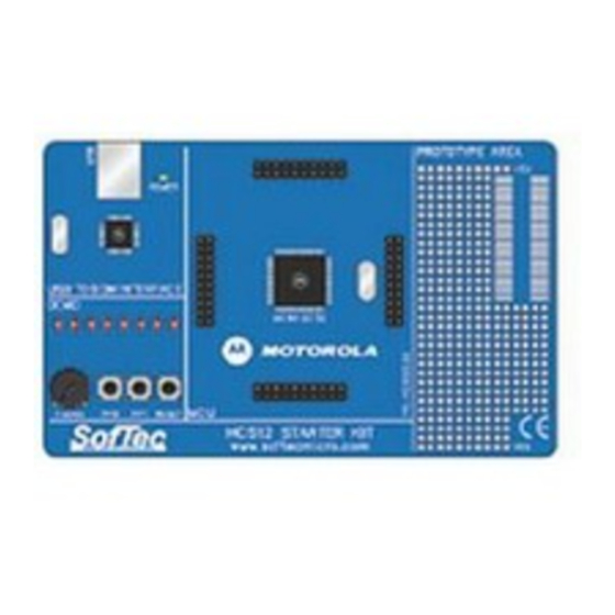
PK-HCS12E128 User's Manual 1. Overview What is the PK-HCS12E128 Starter Kit? The PK-HCS12E128 Starter Kit is an entry level tool which allows you to get started with the Motorola MC9S12E128 microcontroller. The main features of the MC9S12E128 microcontroller are: §... - Page 7 Full-speed program execution allows you to perform hardware and software testing in real time. PK-HCS12E128 is connected to the host PC through a USB port. A prototyping area allows you to wire your own small application.
-
Page 8: Background Debug Module (Bdm)
1. A “USB to BDM Interface” section. It contains the circuitry needed to electrically and logically translate BDM-like commands sent by the host PC through the USB cable to the BDM interface of the microcontroller. The PK-HCS12E128 board is powered (at 5 V) by the USB bus. -
Page 9: Codewarrior Integrated Development Environment
1. Overview The PK-HCS12E128 Board CodeWarrior Integrated Development Environment PK-HCS12E128 comes with a free version of CodeWarrior Development Studio for HC(S)12 Microcontrollers, Special Edition. CodeWarrior Development Studio for HC(S)12 is a powerful and easy-to-use tool suite designed to increase your software development productivity. Its Integrated Development... -
Page 10: Recommended Reading
Motorola HCS12 Datasheets—Include detailed information on the devices’ background debug module. Software Upgrades The latest version of the PK-HCS12E128 system software is always available free of charge from our website: http://www.softecmicro.com. Metrowerks CodeWarrior upgrades can be found at http://www.metrowerks.com. Page 9... -
Page 12: Getting Started
6. This user’s manual. Host System Requirements The PK-HCS12E128 in-circuit debugger is controlled by an Integrated Development Environment running under Windows (CodeWarrior HC(S)12). The following hardware and software are required to run the CodeWarrior HC(S)12 user interface together with PK- HCS12E128: 1. -
Page 13: Installing The Software
2. Getting Started Installing the Software Note: before to connect the PK-HCS12E128 board to the PC, it is recommended that you install all of the required software first (see below), so that the PK-HCS12E128 USB driver will be automatically found by Windows when you connect the board. -
Page 14: Installing The Hardware
2. Insert one end of the USB cable into a free USB port. 3. Insert the other end of the USB cable into the “USB” connector on the PK-HCS12E128 board. The green “POWER” LED on the instrument should turn on. Windows will automatically recognize the instrument and will load the appropriate USB driver. - Page 15 ADC peripheral) and displays this value on the LEDs. To execute the sample application, follow the next steps: 1. Ensure that the PK-HCS12E128 board is connected to the PC (via the USB cable). 2. Start the CodeWarrior HC(S)12 IDE by selecting Start > Programs > Metrowerks CodeWarrior >...
- Page 16 PK-HCS12E128 User's Manual The Example’s Source Code 5. From the main menu, choose Project > Debug. This will compile the source code, generate an executable file and download it to the PK-HCS12E128 board. 6. A new debugger environment will open. Page 15...
- Page 17 7. From the main menu, choose Run > Start/Continue. The program will be executed in real-time. By rotating the potentiometer on the PK-HCS12E128 board, you affect the results of the A/D conversion, and the value of each conversion is displayed on the LEDs.
-
Page 18: Additional Examples
PK-HCS12E128 User's Manual 9. From the main menu, choose Run > Single Step. The instruction highlighted in the Source window will be executed, and the program execution will be stopped immediately after. 10. In the Source window, insert a breakpoint at the “PTT = ATDDR0H;” instruction in the main function. -
Page 20: Hardware Features
Contrariwise to traditional in-circuit emulation (where the target application is executed and emulated inside the emulator), PK-HCS12E128 uses the very same target microcontroller to carry on in-circuit execution. This means that all microcontroller’s peripherals (timers, A/D converters, I/O pins, etc.) are not reconstructed or simulated by an external device, but are... -
Page 21: Usb To Bdm Interface
USB cable, we have decided to use a standard USB cable. We therefore recommend that you use the PK-HCS12E128 board with the USB cable provided or, if you use another USB cable, ensure that the cable length does not exceed 2 meters. -
Page 22: Prototype Area
PK-HCS12E128 User's Manual § Two user push-buttons, connected to the microcontroller’s PAD04 and PAD05 pins. In order to read the status of these two push-buttons, the microcontroller’s internal pull-ups must be enabled (through software) on these pins. § One push-button connected to the microcontroller’s RESET pin. -
Page 24: Debugging Features
Using the Project Wizard to Create Your Application Skeleton CodeWarrior HC(S)12 helps you get started with your own application by including a project wizard specific for HCS12-based SofTec Microsystems boards. To create a new PK- HCS12E128 project: 1. From the main menu, select File > New. -
Page 25: Starting Your First Debugging Session
4. Debugging Features Note: in step 7 of the project wizard, make sure to select “inDART-HCS12 Hardware Debugging” as the connection for your project (the PK-HCS12E128 board is based on the SofTec Microsystems’ inDART debugging engine). Starting your first Debugging Session The first time you enter a debugging session (by selecting Project >... -
Page 26: Using Existing Projects With Pk-Hcs12E128
If your project has been targeted to an emulator/simulator other than PK-HCS12E128 and you wish to use PK-HCS12E128 as the debugger for your project, please do the following: 1. If your project has been created with a version of CodeWarrior less than 3.0, make sure that the “target”... - Page 27 The Set Target Dialog Box 3. A dialog box will appear asking you to locate the GDI DLL file needed to interface with PK-HCS12E128. Select the SofTec_BDM12.dll file located into the \Program Files\Metrowerks\CodeWarrior CW12\prog\ directory. The GDI Setup Dialog Box 4.
-
Page 28: Breakpoints And Trace
PK-HCS12E128 User's Manual The MCU Configuration Dialog Box 5. On the CodeWarrior HC(S)12 debugger interface a new menu (inDART-HCS12) will be created. From this menu, select Load and locate the object file your project is based on. Breakpoints and Trace CodeWarrior offers a variety of tools for analyzing the program flow: breakpoints (both simple and complex), watchpoints and a trace buffer. -
Page 29: Notes And Tips
4. Debugging Features Note: the Single Step command (in a C source code) and the Step Over and Step Out commands (both in a C and Assembly source code) use one hardware breakpoint. Notes and Tips Entering Debug Session with CodeWarrior When entering a debug session, the target microcontroller’s FLASH memory is automatically erased, unsecured and programmed with the user application. -
Page 30: Stop Assembly Instruction
PK-HCS12E128 User's Manual STOP Assembly Instruction The BDM peripheral doesn’t work in STOP mode. If, on the Condition Code Register (CCR), the S bit is set, the STOP instruction will stop all the microcontroller’s activities (and therefore the BDM peripheral). If, on the other hand, the S bit is reset, the STOP instruction will be executed as two NOP instructions. -
Page 31: Hardware Breakpoints And Software Breakpoints
4. Debugging Features PK-HCS12E128 always sets the CLKSW bit to 0: you are therefore free to change the microcontroller’s bus frequency through the PLL, since this will not affect the BDM communication. Note: PK-HCS12E128 uses the 16 MHz external oscillator as the clock source for the BDM communication. -
Page 32: Datablaze Programming Utility
§ Serial numbering. Note: due to the evaluation purposes of the PK-HCS12E128 starter kit (and therefore to the slow data transfer rate from the PC to the target and vice versa), the DataBlaze programming utility takes a long time to write to/read from the whole microcontroller memory. -
Page 33: Datablaze Notes
4. Debugging Features The DataBlaze User Interface DataBlaze Notes § The “Mass Erase” operation always blanks the device (even if the device is protected or secured) and “unsecures” the device (the FLASH Options/Security Byte location is programmed with 0xFE). § The “Blank Check”... - Page 34 PK-HCS12E128 User's Manual § In case of verifying error, please verify the value programmed to the FLASH Options/Security Byte location. The bit 0 of this byte is always programmed to 0, so any attempt to program it to 1 will cause a verifying error.
-
Page 36: Troubleshooting
This section reports some common problems that may arise during general use. Communication Can’t Be Established with PK-HCS12E128 1. Make sure the PK-HCS12E128 starter kit is connected to the PC and powered on. PK- HCS12E128 is powered by the USB connection. -
Page 37: Stepping Execution Is Slow
SofTec Microsystems offers its customers a free technical support service at support@softecmicro.com. Before getting in contact with us, we advise you to check that you are working with the latest version of the PK-HCS12E128 system software (upgrades are available free of charge at http://www.softecmicro.com). Additional resources can be found on our HCS12 online discussion forum. -
Page 38: Appendix A. Electrical And Physical Specifications
PK-HCS12E128 User's Manual Appendix A. Electrical and Physical Specifications Operating Voltage 4.75 to 5.0 V DC (provided by the USB connection) Power Consumption 200 mA (max) Dimensions 137 x 86 x 15 mm Weight 55 g Operating Temperature 0 °C to 50 °C Storage Temperature -20 °C to 70 °C...
Need help?
Do you have a question about the PK-HCS12E128 and is the answer not in the manual?
Questions and answers