Table of Contents
Advertisement
Quick Links
Advertisement
Table of Contents

Subscribe to Our Youtube Channel
Related Manuals for CONTINENTAL EDISON CECP551FSA


Summary of Contents for CONTINENTAL EDISON CECP551FSA
- Page 1 CECP551FSA Manuel d’instructions de la PLAQUE DE CUISSON INDUCTION...
- Page 2 Cooking Hob CECP551FSA Cooking Zones INDUCTION 220-240V 50/60 Hz Supply Voltage 400 V 50/60 Hz Installed Electric Power 5500 Product Size 590×520×55 D×W×H(mm) 560×490 Building-in Dimensions A×B (mm) Induction Hotplate Appearance...
-
Page 3: Product Introduction
Dear customer: Thank you for purchasing the the induction hotplate our product can serve you many years to your satisfaction. Please read this instructions manual carefully before using and installation, keep it cautiously after reading for future reference. Thank you for your purchase of the induction hotplate again, and wish you to enjoy the pleasure by it. - Page 4 Over- Temperature Protection A temperature sensor equipped can monitor the temperature inside the hotplate. When an excessive temperature is monitored, the induction hotplate will stop operation automatically. Pot Detection When an unsuitable size or non-magnetic pot (e.g. Aluminum), or some other small item (e.g.
-
Page 5: Selection Of Installation Equipment
Selection of installation equipment Drill holes on the table surface according to the sizes shown in the drawing. For the purpose of installation and use, a minimum of 50 mm space shall be preserved around the hole. Be sure the thickness of the table surface is at least 30mm. Please select heat-resistant table material to avoid larger deformation caused by the heat radiation from the hotplate. - Page 6 Note: The safety distance between the hotplate and the cupboard above the hotplate should be at least 760mm. Fix the hob on the table by screw four brackets on the bottom of hob (as shown in figure (4)) after installation. Adjust the bracket position to suit for different table top thickness.
-
Page 7: Power Line Connection
Warning • Always check before any electrical operation, the supply tension shown on the electricity meter, the adjustment of the circuit breaker, the continuity of the connection to earth to the installation and that the fuse is suitable. • The electrical connection to the installation should be made via a socket with a plug with earth, or via an Omni-pole cut-out switch with an opening gap of at least 3 mm. - Page 8 If the cable is damaged or needed to be replaced, the operation must be carried out by the after-sale agent with dedicated tools to avoid any accidents. If the appliance is being connected directly to the mains an Omni-polar circuit-breaker must be installed with a minimum opening of 3mm between contacts.
- Page 9 Schematic Diagram of The Control Panel Timer Regulating key Lock Power Regulating key Figure (7) Instructions For Use Preparation Before Using: After power on, the buzzer beep once, all the indicators light up for 1 second and then go out, which indicates the induction hotplate enters the state of standby. Put the pot in the center of the heating zone.
-
Page 10: Timing Function
See the attached table “the max. power of each heating zone” for the power specific to each heating zone. Note: 1. After the “ON/OFF” button is pressed, the induction hotplate will restore to its standby state if no any operation is carried out within one minute. Timing function Select the relevant cooking zone, and set the power level with the “+”... -
Page 11: Interlock Function
Note: 1. In the timing state, the power level of the relevant cooking zone can be changed, and the time set is still valid. 2. Press the “+” or “-“of timing button without select one cooking zone when the induction hotplate is working, the time-warning function will operate. And the warning time can be set just like the timing function. - Page 12 Selection of heating appliances Iron oil frying pan Stainless steel pot Iron pan Iron kettle Enamel stainless Enamel cooking Iron plate steel kettle utensil You may have multiple appliances suitable for heating. This induction hotplate is able to identify multiple heating appliances, and you can test them according to one of the following methods: 1.
- Page 13 Never have the induction For sealed food such as After being used for a hotplate to work without canned goods, please long time, food inside, otherwise its do not heat them before corresponding heating operational performance opening their covers so zone of the induction may be affected and as to avoid any dangers...
- Page 14 Clean induction Keep electrical If the supply cord is hotplate on a regular appliance out of reach damaged , it must be basis to prevent foreign from children or inform replaced matters from entering the person. Do not let them manufacturer, fan thus influencing the appliances...
- Page 15 Cleanness and Maintenance You can easily clean the surface of the induction hotplate if following the methods given in the table. Type of Articles used Method of cleaning contamination forcleaning Immerse in hot water then wipe it Light Cleaning sponge Special cleaning Accumulation...
-
Page 16: Failure Display And Inspection
Failure Display and Inspection If an abnormality comes up, the induction hotplate will enter the protective state automatically and display corresponding protective codes: Troubles Possible reasons Solutions F0-F2 Fan failure. Please contact the supplier Power on, and then restart after the Thermistor component temperature around returns to be... - Page 17 Customer Care Service Before calling the After Sales Service In case the appliance should not work correctly we suggest to: -verify if the plug is correctly inserted in the socket -read the Failure and Display table above In case it is not possible to establish the reason for the bad functioning of the appliance, switch it off, do not try to manumit it and call the After Sales Service.
- Page 18 Cooking Hob CECP551FSA Cooking Zones 3 INDUCTION 220-240V 50/60 Hz Supply Voltage 400 V 50/60 Hz Installed Electric Power 5500 Product Size 590×520×55 D×W×H(mm) 560×490 Building-in Dimensions A×B (mm) Induction Hotplate Appearance...
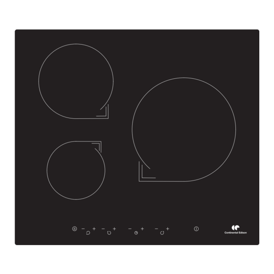
- Page 19 CECP551FSA Figure (1)
- Page 20 u ’ e l l é t t é s t i l i s ) é é é t é s n i ’ « » a ’ i f f é i t c é v s è ’...
- Page 21 Figure (2) mini 5 cm mini 5 mm mini 2 cm Figure (3)
- Page 22 Figure (4)
- Page 23 400V 220-240V 220-240V 220-240V 220-240V 220-240V Connectez à l’alimentation principale Connectez à l’alimentation principale Connectez à l’alimentation principale 220-240V 2+2N~ 400V~ 2-N 220-240V~ Figure (5)
- Page 24 Figure (6) Schéma du tableau de commande Touche de sélection de zone de chauffage Touche Minuteur Clé (Dispositif sécurité) Touche de réglage Figure (7)
-
Page 25: Fonction Minuterie
Mode d'emploi Préparation avant utilisation: Après avoir allumé les plaques, le signal sonore sonnera une fois et tous les voyants s’allumeront pendant 1 seconde puis s’éteindront, ce qui indique que la touche des plaques entre en état de veille. Instructions de fonctionnement Lorsque vous appuyez sur la touche Marche/arrêt, tous les indicateurs affichent -»... -
Page 26: Annulation De La Minuterie
Appuyez sur le bouton « Minuterie », l’indicateur de minuterie clignote, et vous pouvez alors régler la minuterie à ce moment-là. Appuyez sur le boutton « + » et « - », vous pouvez régler les paramètres du minuteur de 0 à 99 minutes. Lorsque vous appuyez sur la touche «... -
Page 27: Fonction Sécurité Enfants
Remarque : 1. Lorsque la minuterie est enclenchée, il est possible de changer la puissance de cuisson, le temps de minuterie restera valide. 2. Appuyez sur le bouton de minuterie "+" ou "-" sans avoir sélectionné une plaque de cuisson alors que la plaque à induction est allumée, la fonction d’alarme sera accessible. - Page 28 Fonction Réchauffer : Heating Zone Power(W) Dia. Of the Heating Zone 1500 140mm 2000 180mm 250mm 2000...
- Page 32 F0 -F2 F3-F8 F9 -F IGBT E1/E2 E3/E4 E5/E6...
Need help?
Do you have a question about the CECP551FSA and is the answer not in the manual?
Questions and answers