Table of Contents
Advertisement
USER GUIDE AND SPECIFICATIONS
NI myDAQ
Contents
Français
Deutsch
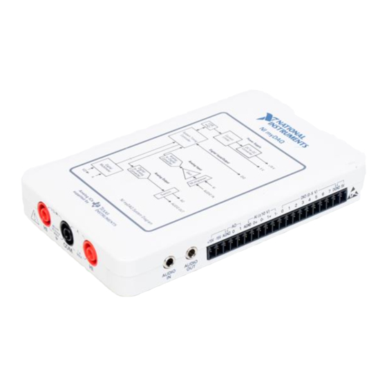
NI myDAQ is a low-cost portable data acquisition (DAQ) device that uses
NI LabVIEW-based software instruments, allowing students to measure
and analyze real-world signals. NI myDAQ is ideal for exploring
electronics and taking sensor measurements. Combined with NI LabVIEW
on the PC, students can analyze and process acquired signals and control
simple processes anytime, anywhere.
Conventions ............................................................................................ 3
Safety Information .................................................................................. 3
Electromagnetic Compatibility Guidelines............................................. 3
ni.com/manuals
Figure 1. NI myDAQ
Advertisement
Table of Contents

Related Manuals for National Instruments myDAQ 195509D-01L


Summary of Contents for National Instruments myDAQ 195509D-01L
- Page 1 USER GUIDE AND SPECIFICATIONS NI myDAQ Français Deutsch ni.com/manuals Figure 1. NI myDAQ NI myDAQ is a low-cost portable data acquisition (DAQ) device that uses NI LabVIEW-based software instruments, allowing students to measure and analyze real-world signals. NI myDAQ is ideal for exploring electronics and taking sensor measurements.
-
Page 2: Table Of Contents
NI myDAQ Hardware Overview.............4 Analog Input (AI) ................5 Analog Output (AO).................6 Digital Input/Output (DIO)...............6 Power Supplies .................6 Digital Multimeter (DMM) ..............7 NI myDAQ Software Overview ..............7 NI ELVISmx Driver Software............7 NI LabVIEW and NI ELVISmx Express VIs ........7 NI myDAQ and NI Multisim ............8 Getting Started ..................8 Making Signal Connections with NI myDAQ ........9 Setting up Your NI myDAQ Device ..........9... - Page 3 Misuse of the hardware can result in a hazard. You can compromise the safety protection if the hardware is damaged in any way. If the hardware is damaged, return it to National Instruments for repair. Clean the hardware with a soft, nonmetallic brush. Make sure that the hardware is completely dry and free from contaminants before returning it to service.
-
Page 4: Ni Mydaq Hardware Overview
Furthermore, any changes or modifications to the product not expressly approved by National Instruments could void your authority to operate it under your local regulatory rules. NI myDAQ Hardware Overview NI myDAQ provides analog input (AI), analog output (AO), digital input and output (DIO), audio, power supplies, and digital multimeter (DMM) functions in a compact USB device. -
Page 5: Analog Input (Ai)
Analog inputs can be measured at up to 200 kS/s per channel, so they are useful for waveform acquisition. Analog inputs are used in the NI ELVISmx Oscilloscope, Dynamic Signal Analyzer, and Bode Analyzer instruments. © National Instruments Corporation NI myDAQ User Guide and Specifications... -
Page 6: Analog Output (Ao)
Analog Output (AO) There are two analog output channels on NI myDAQ. These channels can be configured as either general-purpose voltage output or audio output. Both channels have a dedicated digital-to-analog converter (DAC), so they can update simultaneously. In general-purpose mode, you can generate up to ±10 V signals. -
Page 7: Digital Multimeter (Dmm)
Using NI myDAQ with LabVIEW section. NI ELVISmx supports LabVIEW (32 bit). To use NI ELVISmx with LabVIEW on Note a 64-bit operating system, you must have LabVIEW (32 bit) installed. © National Instruments Corporation NI myDAQ User Guide and Specifications... -
Page 8: Ni Mydaq And Ni Multisim
The computer will recognize the NI myDAQ and the NI ELVISmx Instrument Launcher appears. You can also manually open NI ELVISmx Instrument Launcher by selecting Start»All Programs» National Instruments»NI ELVISmx for NI ELVIS & NI myDAQ» NI ELVISmx Instrument Launcher. NI myDAQ User Guide and Specifications... -
Page 9: Making Signal Connections With Ni Mydaq
The screw terminal connector must snap securely into place to ensure proper signal connection. 1 NI myDAQ 4 20-Position Screw Terminal Connector 2 USB Cable 5 Audio Cable 3 LED 6 DMM Banana Cable Figure 3. NI myDAQ Connection Diagram © National Instruments Corporation NI myDAQ User Guide and Specifications... -
Page 10: Connecting Signals
Connecting Signals Figure 4 shows the available audio, AI, AO, DIO, GND, and power signals accessed through the 3.5 mm audio jacks and screw terminal connections. Refer to Table 1 for descriptions of these signals. Caution Signal wires must be securely affixed and screwed down in the screw terminal connector to ensure proper connection. -
Page 11: Connecting Analog Input Signals
NI myDAQ device, assuming that the computer is plugged into the same power system. Instruments or devices with nonisolated outputs that plug into the building power system are ground-referenced signal sources. © National Instruments Corporation NI myDAQ User Guide and Specifications... - Page 12 Most laptop computers have isolated power supplies, and are consequently not Note connected to the building ground system. In these cases, treat the analog input signal as floating with respect to NI myDAQ. The difference in ground potential between two instruments connected to the same building power system is typically between 1 and 100 mV.
- Page 13 (sum) of the two resistors. If, for example, the source impedance is 2 k and each of the two resistors is 100 k, the resistors load down the source with 200 k and produce a –1% gain error. © National Instruments Corporation NI myDAQ User Guide and Specifications...
-
Page 14: Ni Mydaq Dmm Fuse Replacement
Using a banana cable, connect the HI (V) and HI (A) DMM terminals. Launch the NI ELVISmx Digital Multimeter (DMM) Soft Front Panel instrument from the NI ELVISmx Instrument Launcher, located at Start»All Programs»National Instruments»NI ELVISmx for NI ELVIS & NI myDAQ»NI ELVISmx Instrument Launcher. Select the Resistance mode. - Page 15 Remove the screw terminal connector and all other signal cables from the device. Loosen the four Phillips screws that attach the bottom of the enclosure to the device, and remove the top lid of the enclosure. © National Instruments Corporation NI myDAQ User Guide and Specifications...
- Page 16 Do not remove the board from the bottom half of the NI myDAQ enclosure. Caution Replace the broken fuse while referring to Figure 10 for the fuse location, taking care to not damage any components on the board. 1 Enclosure Screws 2 Internal Fuse—1.25 A Fast-Acting (Littelfuse Part Number 02161.25) Figure 10.
-
Page 17: Digital I/O (Dio) And Counters/Timers
NI myDAQ, refer to the KnowledgeBase document How Do I Use the NI myDAQ Counter?. To access this document, go to and enter the Info Code ni.com/info mydaqcounter © National Instruments Corporation NI myDAQ User Guide and Specifications... -
Page 18: Using Ni Mydaq With Soft Front Panel (Sfp) Instruments
NI ELVISmx Instrument Launcher features, refer to the NI ELVISmx Help. To access this help file, go to Start» All Programs»National Instruments»NI ELVISmx for NI ELVIS & NI myDAQ» NI ELVISmx Help. -
Page 19: Ni Elvismx Instrument Launcher
NI myDAQ device, the NI ELVISmx Instrument Launcher automatically opens. To manually open the Instrument Launcher, navigate to Start»All Programs»National Instruments»NI ELVISmx for NI ELVIS & NI myDAQ»NI ELVISmx Instrument Launcher. This opens the suite of LabVIEW SFP instruments. -
Page 20: Digital Multimeter (Dmm)
Digital Multimeter (DMM) The NI ELVISmx Digital Multimeter (DMM) is a stand-alone instrument that controls the basic DMM capabilities of NI myDAQ. This commonly used instrument can perform the following types of functions: • Voltage measurement (DC and AC) • Current measurement (DC and AC) •... -
Page 21: Oscilloscope (Scope)
200 ms to 5 s. • Trigger settings: Immediate and Edge Trigger Types are supported. When using Edge Trigger Type, you can specify a Horizontal Position of 0%–100%. Figure 13. NI ELVISmx Oscilloscope SFP © National Instruments Corporation NI myDAQ User Guide and Specifications... -
Page 22: Function Generator (Fgen)
Function Generator (FGEN) The NI ELVISmx Function Generator (FGEN) generates standard waveforms with options for the type of output waveform (sine, square, or triangle), amplitude selection, and frequency settings. In addition, the instrument offers DC offset setting, frequency sweep capabilities, and amplitude and frequency modulation. -
Page 23: Bode Analyzer
Op-Amp signal polarity. Refer to the NI ELVISmx Help for required hardware connections. To access this help file, go to Start» All Programs»National Instruments»NI ELVISmx for NI ELVIS & NI myDAQ»NI ELVISmx Help. This instrument has the following measurement parameters: •... -
Page 24: Dynamic Signal Analyzer (Dsa)
Dynamic Signal Analyzer (DSA) The NI ELVISmx Dynamic Signal Analyzer (DSA) performs a frequency domain transform of the AI or Audio Input waveform measurement. It can either continuously make measurements or make a single scan. You can also apply various window and filtering options to the signal. This instrument has the following measurement parameters: •... -
Page 25: Arbitrary Waveform Generator (Arb)
AudioOutput Right. You can use AO channels or AudioOutput channels, but not a combination of both. • Trigger Source: Immediate only. This control will always be disabled. Figure 17. NI ELVISmx Arbitrary Waveform Generator SFP © National Instruments Corporation NI myDAQ User Guide and Specifications... -
Page 26: Digital Reader
Digital Reader The NI ELVISmx Digital Reader reads digital data from the NI myDAQ digital lines. NI ELVISmx Digital Reader groups the I/O lines into ports through which data can be read. You can read one port at a time, either continuously or as a single reading. -
Page 27: Digital Writer
NI myDAQ. Figure 19. NI ELVISmx Digital Writer SFP © National Instruments Corporation NI myDAQ User Guide and Specifications... -
Page 28: Example: Measuring A Signal Using The Ni Elvismx Oscilloscope Sfp With Ni Mydaq
Example: Measuring a Signal Using the NI ELVISmx Oscilloscope SFP with NI myDAQ Complete the following steps to measure a signal with the NI ELVISmx Scope SFP. Note Before opening a SFP, make sure that the NI myDAQ device is connected to the system and is ready to use. -
Page 29: Using Ni Mydaq With Labview
Table 4 shows the available NI ELVISmx Express VIs. Refer to the NI ELVISmx Help for more information. To access this help file, go to Start»All Programs»National Instruments»NI ELVISmx for NI ELVIS & NI myDAQ»NI ELVISmx Help. Table 4. NI ELVISmx Express VIs for NI myDAQ NI ELVISmx Express VI —... -
Page 30: Example: Measuring Signals Using The Ni Elvismx Oscilloscope Express Vi With Ni Mydaq
Example: Measuring Signals Using the NI ELVISmx Oscilloscope Express VI with NI myDAQ Complete the following steps to use the NI ELVISmx Oscilloscope to measure a signal. Note For more information on grounding the signals, refer to the Connecting Analog Input Signals section. - Page 31 Channel 1 if you configured the NI ELVISmx Oscilloscope Express VI to enable Channel 1. 10. Click the Run button to begin acquiring the measurement. You should see the signal(s) in the graphs on the VI front panel. © National Instruments Corporation NI myDAQ User Guide and Specifications...
-
Page 32: Using Ni-Daqmx With Ni Mydaq
Using NI-DAQmx with NI myDAQ NI myDAQ is supported by NI-DAQmx, and therefore you can program it using the DAQ Assistant Express VI. Figure 20 shows the DAQ Assistant Express VI. Figure 20. DAQ Assistant Express VI Note In NI-DAQmx, DIO <0..7> appear as P0.<0..7>. Furthermore, you can use NI-DAQmx to program some of the available general AI, AO, and timing functionality of the device. - Page 33 DAQ Assistant Express VI on the block diagram. The DAQ Assistant Create New Express Task configuration window opens. 12. In the DAQ Assistant configuration window, select Generate Signals» Analog Output, and click Voltage to select a Voltage task. © National Instruments Corporation NI myDAQ User Guide and Specifications...
- Page 34 13. In the Supported Physical Channels window, select audioOutputLeft from under the Devx (NI myDAQ) option. You can also press <Ctrl> while clicking audioOutputRight to select both channels. 14. Click Finish to exit the Create New Express Task dialog. 15. On the Configuration tab of the DAQ Assistant front panel window, configure voltage channel 0 by selecting VoltageOut_0 in the Channel Settings pane, and setting Max to and Min to...
- Page 35 This example provides the basis for audio measurement. Experiment further by placing digital signal processing steps such as filters between the input and output. © National Instruments Corporation NI myDAQ User Guide and Specifications...
-
Page 36: Specifications
Specifications Performance is typical after a three-minute warmup, at 23 °C unless otherwise specified. This document may not contain the most recent published specifications. To get the most recent edition of this document, go to and enter into the Search field. ni.com/manuals mydaq Analog Input... - Page 37 Figure 21. Settling Time (10 V Range) versus Different Source Impedance 2 kΩ 5 kΩ 10 kΩ –0.2 Sample Rate (kHz) Figure 22. Settling Time (2 V Range) versus Different Source Impedance © National Instruments Corporation NI myDAQ User Guide and Specifications...
- Page 38 Input FIFO size ........4,095 samples, shared among channels used Maximum working voltage for analog inputs (signal + common mode) .....±10.5 V to AGND Common-mode rejection ratio (CMRR) (DC to 60 Hz)....70 dB Input impedance Device on AI+ or AI– to AGND ....>10 G || 100 pF AI+ to AI–...
- Page 39 Direction control ........Each line individually programmable as input or output Update mode .......... Software-timed When powered on, the analog output signal is not defined until after USB configuration is complete. © National Instruments Corporation NI myDAQ User Guide and Specifications...
- Page 40 Pull-down resistor........75 k Logic level ..........5 V compatible LVTTL input; 3.3 V LVTTL output min ...........2.0 V max...........0.8 V Maximum output current per line ..4 mA General Purpose Counter/Timer Number of counter/timers.......1 Resolution ..........32 bits Internal base clocks ........100 MHz Base clock accuracy........100 ppm Maximum counting and pulse generation update rate......1 MS/s...
- Page 41 For example, for a 10 V using the DC Volts function in the 20.00 V range, calculate the accuracy using the following equation: 10 V × 0.5% + 20 mV = 0.07 V Input impedance ........10 M © National Instruments Corporation NI myDAQ User Guide and Specifications...
- Page 42 Current Measurement DC ranges ..........20 mA, 200 mA, 1 A AC ranges ..........20 mA , 200 mA , 1 A Note All AC accuracy specifications within 20 mA and 200 mA ranges apply to signal amplitudes greater than 5% of range. All AC accuracy specifications within the 1 A range apply to signal amplitudes greater than 10% of range.
- Page 43 The total power available for the power supplies, analog outputs, and digital outputs is limited to 500 mW (typical)/100 mW (minimum). Refer to the NI myDAQ Hardware Overview section for information on calculating the total power consumption of the components of your system. © National Instruments Corporation NI myDAQ User Guide and Specifications...
- Page 44 –15V Supply Output voltage Typical (no load) ......–15.0 V Maximum voltage with no load..–15.3 V Minimum voltage with full load..–14.0 V Maximum output current .......32 mA Maximum load capacitance ....470 F +5V Supply Output voltage Typical (no load) ......4.9 V Maximum voltage with no load..5.2 V Minimum voltage with full load..4.0 V Maximum output current...
- Page 45 Do not use this module for connection to signals or for measurements within Caution Measurement Categories II, III, or IV. © National Instruments Corporation NI myDAQ User Guide and Specifications...
- Page 46 Safety Standards This product is designed to meet the requirements of the following standards of safety for electrical equipment for measurement, control, and laboratory use: • IEC 61010-1, EN 61010-1 • UL 61010-1, CSA 61010-1 Note For UL and other safety certifications, refer to the product label or the Online Product Certification section.
- Page 47 National Instruments (RoHS) National Instruments RoHS ni.com/environment/rohs_china (For information about China RoHS compliance, go to ni.com/environment/rohs_china © National Instruments Corporation NI myDAQ User Guide and Specifications...
-
Page 48: Texas Instruments Components In Ni Mydaq
Texas Instruments Components in NI myDAQ Integrated circuits supplied by Texas Instruments form the power and analog I/O subsystems of NI myDAQ. Figure 2 depicts the arrangement and function of the NI myDAQ subsystems. Table 5 lists all of the Texas Instruments components used in NI myDAQ. - Page 49 150 mW of continuous RMS power per channel into 16 -loads. Buffer SN74AUP1G17 This is a low-power Schmitt-Trigger buffer. Switch TS12A44514 This is a low on-state resistance quad SPST CMOS analog switch. © National Instruments Corporation NI myDAQ User Guide and Specifications...
-
Page 50: Resource Conflicts
Resource Conflicts Table 6 summarizes the resource conflicts you might encounter if you run certain NI myDAQ circuitry simultaneously. To use the information in Table 6, find the instrument you want to use in the left column. That row lists all the functions that are resource conflicts. If the intersecting box contains an —, you can use those functions simultaneously without any conflicts. - Page 51 Table 6. NI myDAQ Resource Conflicts Scope Scope (AI) (Audio) FGEN Bode (AI) (Audio) (AO) (Audio) (4 Lines) (8 Lines) (4 Lines) (8 Lines) — — — — — — — — — — — — — Scope ...
-
Page 52: Additional Resources
NI ELVISmx Help—This help file contains information about the NI ELVISmx software, including information on using NI ELVISmx SFP instruments and NI ELVISmx Express VIs. To access this help file, go to Start»All Programs»National Instruments»NI ELVISmx for NI ELVIS & NI myDAQ»NI ELVISmx Help. LabVIEW •... -
Page 53: Other Resources
AI, AO, DIO, GND, and power signals. Programmable Function A signal that can be configured for different uses, such Interface as a digital input, a digital output, a timing input, or a timing output. © National Instruments Corporation NI myDAQ User Guide and Specifications... -
Page 54: Warranty
For patents covering National Instruments products/technology, refer to the appropriate location: Help»Patents in your software, the patents.txt file on your media, or the National Instruments Patent Notice at ni.com/patents. Refer to the Export Compliance Information at ni.com/legal/ export-compliance for the National Instruments global trade compliance policy and how to obtain relevant HTS codes, ECCNs, and other import/export data.
Need help?
Do you have a question about the myDAQ 195509D-01L and is the answer not in the manual?
Questions and answers