Table of Contents
Advertisement
Quick Links
INSTALLATION MANUAL
• Please read this installation manual completely before installing the product.
• Installation work must be performed in accordance with the national wiring
standards by authorized personnel only.
• Please retain this installation manual for future reference after reading it
thoroughly.
TYPE : Dry contact for demand control
MODEL : PQDSBCDVM0
P/NO : MFL42540219
www.lg.com
Advertisement
Table of Contents

Subscribe to Our Youtube Channel
Related Manuals for LG V-net PQDSBCDVM0


Summary of Contents for LG V-net PQDSBCDVM0
- Page 1 • Installation work must be performed in accordance with the national wiring standards by authorized personnel only. • Please retain this installation manual for future reference after reading it thoroughly. TYPE : Dry contact for demand control MODEL : PQDSBCDVM0 www.lg.com P/NO : MFL42540219...
-
Page 2: Table Of Contents
Dry contact for demand control Installation manual TABLE OF CONTENTS I Safety Precautions..................3 I Name of each part ..................5 I Accessory Parts..................6 I Installation Method..................7 I Setting and using method ...............8 1. Power source input ..................8 2. System structure ...................9 3. -
Page 3: I Safety Precautions
Safety Precautions Safety Precautions To prevent injury to the user or other people and property damage, the following instructions must be followed. I Incorrect operation due to ignoring instruction will cause harm or damage. The seriousness is classified by the following indications. WARNING This symbol indicates the possibility of death or serious injury. - Page 4 Safety Precautions I During use Do not modify or extend the Do not use any flaming Do not use any heating power cord. devices near the product. devices near the power cord. • It can cause a fire and • It can cause a fire. •...
-
Page 5: I Name Of Each Part
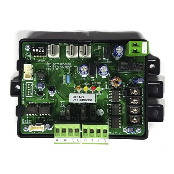
Name of each part Name of each part DRY CONTACT FOR DEMAND CONTROL 1. SWDIP : Switch to select main function 2. SW_Address2 : Switch to set a upper address of the outdoor unit 3. SW_Address1 : Switch to set a lower address of the outdoor unit 4. -
Page 6: I Accessory Parts
Accessory Parts Accessory Parts Multi-V ODU Dry contact BRACKET (1EA) SCREW (4EA) PQDSBCDVM0 Sub cable Multi-V WIRE ASSY 1(1EA) WIRE ASSY 2(1EA) Others : Tie Wrap (3 EA) - Cable Tie Clamp (1 EA) 6 Dry contact for demand control... -
Page 7: I Installation Method
Installation Method Installation Method ① Connect the connection wires according to the instructions. (Please refer to Setting and Using Method) ② Perform the switch setting according to switch setting method. (Please refer to Setting and Using Method) ③ Fix the Dry contact on suitable space inside of the outdoor unit. 1. -
Page 8: I Setting And Using Method
Setting and using method Setting and using method After change any Dry contact setting, then you must press RESET switch to reflect the setting. 1. Power source input I When wiring power source from outdoor unit DC12V or DC15V Outdoor Unit I I When using external power source DC12V Power Source... -
Page 9: System Structure
Setting and using method 2. System structure I When outdoor unit has RS-485 communication function (Master Mode) RS-485 BUS_A BUS_B I When outdoor unit doesnʼt have RS-485 communication function (Slave Mode) Multi-V WIRE ASSY 1(1EA) CN_OUT Notes This dry contact module is available after MultiV3 series. Installation manual 9... - Page 10 Setting and using method I When using ODU Dry contact with Central Control Devices (Slave Mode) Multi-V WIRE ASSY 1(1EA) BUS_A Central Control BUS_B Devices CN_OUT Notes This dry contact module is available after MultiV3 series. 10 Dry contact for demand control...
-
Page 11: Connection With Outdoor Unit
Setting and using method 3. Connection with Outdoor unit I I When outdoor unit has RS-485 communication function (RS-485 Built-in model) Outdoor unit INT.A INT.B RS_485 I When outdoor unit doesnʼt have RS-485 communication function Outdoor unit Connector for PI485 CN_OUT Installation manual 11... -
Page 12: Setting Of Input Signal
I When using contact signal input without external power SW_VOLT2 SW_VOLT1 Notes Do not input the voltage signal in LG does not "NON VOLT" setting mode otherwise supply this section it will cause serious damage (Field supply) I When using contact signal input with external power... - Page 13 Setting and using method I When using analog input signal SW_VOLT2 SW_VOLT1 DC 0~10V input Direct Digital Controller Notes • When using an analog signal, Central control Devices can not be used together. Do not use signal cable over 1meter. •...
-
Page 14: Setting Of ʻSwdipʼ
Setting and using method 5. Setting of ʻSWDIPʼ I Using ʻSWDIPʼ, select the option of control function as described below L1 2 3 4 Notes Default State is L1: ON, L2: ON Position Function ON : Master Mode OFF : Slave Mode L1 2 3 4 ON : Enable Low Noise Operation OFF : Disable Low Noise Operation... -
Page 15: Setting Of ʻSw_Stepʼ
Setting and using method 6. Setting of ʻSW_STEPʼ I Use the ʻSW_SETPʼ to set a control step for contact signal input. : The type of input signal and control step can be set using ʻSW_STEPʼ SW_STEP - Type of input signal SW_STEP Input Signal 0, 1, 2, 3, 4, 5, 6... - Page 16 Setting and using method Comp capacity SW_ STEP Input_1 Input_2 Input_3 Type of input Of outdoor unit(%) No control Contact signal ALL OFF No control Contact signal ALL OFF No control Contact signal ALL OFF No control Contact signal COMP OFF ALL OFF Notes •...
- Page 17 Setting and using method - Detail of the control step for analog input signal Comp capacity SW_ STEP Input Voltage Type of input Of outdoor unit(%) No control COMP OFF ALL OFF Analog input COMP OFF Notes • Do not change a command too quickly. Keep the command 30 seconds at least, otherwise it will cause a damage to outdoor unit.
-
Page 18: Setting Of ʻSw_Addressʼ
Setting and using method 7. Setting of ʻSW_Addressʼ I Use the ʻSW_Addressʼ to set an address of outdoor unit - Master Mode use SW_ADDRESS2 to set a group(0~F) If you set a group as “0”, the address of outdoor unit should be “00~0F” - Slave Mode (when using with central control device) use all to set the address of outdoor unit for sending to central control device. -
Page 19: Outdoor Unit Monitoring
Setting and using method 8. Outdoor unit monitoring I Monitoring outdoor unit error : Refer to below and connect to the control device that you want to control. Field Supply Power Error Display AC or DC (Depends on Operation display power type) Notes •... - Page 20 20 Dry contact for demand control...
Need help?
Do you have a question about the V-net PQDSBCDVM0 and is the answer not in the manual?
Questions and answers