
Subscribe to Our Youtube Channel
Related Manuals for ITV U-Prox IP560

Summary of Contents for ITV U-Prox IP560
- Page 1 Wireless access control panel U-Prox IP560 Instruction manual W i r e l e s s a c c e s s c o n t r o l p a n e l w i t h b u i l t i n r e a d e r...
- Page 2 Integrated Technical Vision Ltd. About this document his manual covers installation, adjustment and use of U-Prox IP560 (hereinafter panel) wireless single door access control panel. Read this manual carefully prior to installing the system. Characteristics, Intended use and parameters of the panel are described in the section "Summary".
-
Page 3: Table Of Contents
Integrated Technical Vision Ltd. Contents Brief description of the panel ......................4 Intended use ..........................4 Summary ........................... 4 Description and operation ......................5 Panel ............................5 Panel terminals assignment ....................6 Annunciation of panel readers ....................7 Panel operation ..........................7 ID entry (card pass) ........................ -
Page 4: Brief Description Of The Panel
Panel operates both standalone and in system. U-Prox IP560 panel provides control of one or two actuators. It controls access into the room with one door with one built in reader (single-sided door) or with two readers (double- sided door). -
Page 5: Description And Operation
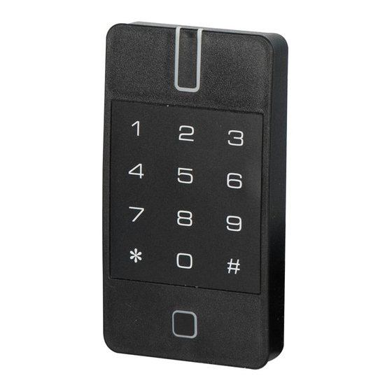
• Weight – 0,2 kG Description and operation Panel The look of the access control panel is shown in Fig. 1 and Fig. 2. Panel enclosure Keypad Built-in RTE button and Bluetooth indicator Fig. 1. U-Prox IP560 panel view http://u-prox.com... -
Page 6: Panel Terminals Assignment
Panel cover and bottom board connection cable Nuts for fixing screw. Bottom may turn on 180 grad at mounting Panel bottom with commutation board. Fig. 2. U-Prox IP560 in general and details Panel terminals assignment Terminal Description Assignment Alarm output Power supply connection... -
Page 7: Annunciation Of Panel Readers
Integrated Technical Vision Ltd. Annunciation of panel readers Current panel access modes indicated by readers connected. It is possible to adjust separate annunciation for each panel with system software. Default annunciation settings are present in table below: Readers’ annunciation Operation mode Normal mode No sound, Red blinks once per second Free pass... -
Page 8: Standalone Mode
Integrated Technical Vision Ltd. Keypad blocked after several sequential wrong (unknown) codes entry or RF ID passes. This function is inactive by default. Press [*] key to cancel erroneous key sequence. The key sequence erased and panel returns to the Normal mode after 40 seconds pause in entry. -
Page 9: Durations
Integrated Technical Vision Ltd. Press [*]. Buzzer beeps three times and LED will light up Amber. Enter old [User code][#]. LED blinks Yellow if correct code entered. Pass new RF ID twice or enter new [User code][#] and confirm with second new [User code][#] entry. New code accepted if its alternation with user was allowed, old code entry was correct and new code not equal to the any other user code or duress code in panel. -
Page 10: Panel Programming In Standalone Mode
Integrated Technical Vision Ltd. • - keypad and reader blocking. LED blinks Red in normal day mode. Panel performs programmed actions on RF ID pass or code entry in this mode. The actions could be Relay#1 and/or Relay#2 activation and a choice of relay for activation. LED is blinks Red and Yellow alternately in normal night mode. - Page 11 Integrated Technical Vision Ltd. Panel name and distance to the panel displayed at scan. Enter engineer’s code on the keypad – panel will allow connection for programming for 40 seconds. Access reject message displayed on attempt to connect without authorization. Select panel from the device list and press ‘Connect’...
- Page 12 Integrated Technical Vision Ltd. The main menu will activate after the settings readout. Advanced options displayed after ‘More’ button pressed. The menu item ‘Save To Device’ became active after settings adjustment. Select ‘Save To Device’ to save changes. http://u-prox.com...
- Page 13 Integrated Technical Vision Ltd. Press ‘Disconnect’ . button to break connection with panel. Attention!!! Disconnection without writing settings will cause changes loss. ‘Settings’ menu item contains main panel settings: “Device” settings group http://u-prox.com...
- Page 14 Integrated Technical Vision Ltd. “Device name” – panel name setting "Firmware" and "Bluetooth firmware" – firmware version and upgrade "Available issue keys" – the number of free cells in memory for identifiers "Master code" - code # 0 change "Engineer’s code" - code # 1 change New code accepted if it is not equal to any other code in system, including duress codes.
- Page 15 Integrated Technical Vision Ltd. "Code match" – keypad blocking duration at code match attempt Allowable values 5 seconds to 4 minutes or code match function disable “Alarm” – alarm output activity duration Allowed values 0 to 240 seconds or deactivation with engineer’s code http://u-prox.com...
- Page 16 Integrated Technical Vision Ltd. "Request to exit button" (RTE) settings group "Mode" – RTE operation modes: "alarm" – Button press activates alarm output "day and night access" – RTE active always "work time access only" – RTE active when panel is in day mode only "day and night modes switch"...
- Page 17 Integrated Technical Vision Ltd. “Door time”– delay duration setting after RTE button press "Front button" – built-in RTE button enabling and disabling (see fig. 1): “Access” settings group " Access Door time" – Sets default value for Entry/exit duration. Allowable values 0 .. 240 seconds or door opened http://u-prox.com...
- Page 18 Integrated Technical Vision Ltd. "Proximity reader" – RF ID type selection: ASK only FSK only or ASK and FSK simultaneously. Attention!!! ASK and FSK modulation is ON by default "Default Relays time" – settings of default duration of Relay #1 and Relay #2 activation Allowable values 0 ..
- Page 19 Integrated Technical Vision Ltd. “Working hours” – Night/Day mode automatic switch schedule. Panel is in day mode inside period of time set and in night mode outside it. Manual switch by passing ID with appropriate option between Night and Day modes possible only if automatic change mode is Off.
- Page 20 Integrated Technical Vision Ltd. ‘Access’ menu item contains the list of codes, enrolled in panel Each list entry contains: • Access type: day – white background, day and night – orange background, or without access – white background • Code name or numeric value of the code if name was not set •...
- Page 21 Integrated Technical Vision Ltd. To enroll new RF ID pass RF ID to the reader. This action adds RF ID to the list of ID’s with default settings. To enroll new keypad code enter it from the keypad finalizing with [#] key. This action adds RF ID to the list of ID’s with default settings.
- Page 22 Integrated Technical Vision Ltd. Click on the link - depending on the settings of smartfone you will be offered to open the link in the U-Prox ID application or in the browser. The U-Prox ID application will automatically start, asking you to confirm the visit. Click the button and select the mail program.
- Page 23 Integrated Technical Vision Ltd. U-Prox Config application or in the browser.The U-Prox Config application will automatically start. After downloading the confirmations, connect to the controller and process the confirmations. Go to the menu item "Access" and select "Approved invites". A confirmation list will open.
- Page 24 Integrated Technical Vision Ltd. To change settings for code select it in the list (nap it). The settings window will open. Change card name and settings. Press ‘Apply’ to save the changes. http://u-prox.com...
- Page 25 Integrated Technical Vision Ltd. It is possible to set personally for each identifier: - access type - Door open duration after the grant of access http://u-prox.com...
- Page 26 Integrated Technical Vision Ltd. - action type after the ID pass - Relay activation duration (if relay selected in item above) Press “Apply” button to save changes. http://u-prox.com...
- Page 27 Integrated Technical Vision Ltd. To change settings for several ids select the first of the identifiers in the list, click on it and hold until it is highlighted in color. Select other identifiers. Next, click - the settings window will open. Change cards settings. Press ‘Apply’...
- Page 28 Integrated Technical Vision Ltd. Use “Upgrade” menu item from advanced options to upgrade panel firmware. The list of available files in *bin format displayed after this item selected. Firmware upgrade process will start after desired file selection. Attention!!! All files with firmware must store in “Download” folder in main mobile device memory.
-
Page 29: Mobile Id
Integrated Technical Vision Ltd. The list of available files with settings will display after “Restore” menu item selection. Select one of them to restore settings into the panel. Mobile ID Download and install U-Prox Mobile ID application. Mobile devices with Android 5.0 OS and higher, Apple 8.0 IOS and higher supported. - Page 30 Integrated Technical Vision Ltd. Press button in application –will exchange data with application. If Bluetooth is not activated on your device application will request for activation, press ‘OK’ Attention! The location services must be ON in Android 6.0 and higher for Smart Bluetooth operation Attention! Button in application will be inactive until any invitation for access is received and confirmed.
- Page 31 Integrated Technical Vision Ltd. Panel will grant access if code where enrolled in it and have correct access rights. Panel and application indication will change. http://u-prox.com...
-
Page 32: In System Operation Mode
Integrated Technical Vision Ltd. In system operation mode Panel controls one door with one or two access points. Access point may be in one of four operation modes: “Normal”, “Alarm”, “Blocked” or “Free pass”. “Free pass” mode has highest priority followed by “Blocked”, “Alarm” and “Normal” in range of priority decrease. -
Page 33: Free Pass" Mode
Integrated Technical Vision Ltd. marked as ‘Lost’ pass, door is open too long and on code matching attempt if last option selected. Panel activates outputs set as ‘Alarm’ and ‘Bell’ in “Alarm” mode. ‘Alarm’ output lasts active during “Alarm” mode. ‘Bell’ output duration is programmable. Access point is blocked for entry if it is in “Alarm”... -
Page 34: Rf Id Properties
(subsequent activation commands alter output state), continuous. The communicator U-Prox IP560 panel operates automatically - after downloading data from the server, it processes the card passed according to its access rights, grants or denies access and sends event messages to the ACS server. - Page 35 Integrated Technical Vision Ltd. U-Prox IP560 panel communicates to the access control system server using ISM band radio interface via U-Prox IC L receiver and U-Prox HE and U-Prox HW repeaters. Panel communicator operates in the notification mode. Panel sends event report message to ACS server on each new event.
- Page 36 Prox IP560 control panels operate in the automatic mode, i.e. make decision about the access using data uploaded beforehand. U-Prox IC L control panel routes data from the allowed U-Prox IP560 wireless panels via U-Prox HE and U-Prox HW repeaters. The U-Prox IP access control system server, U-Prox IC L, U-Prox HE and U-Prox HW communicate each other via the computer network.
-
Page 37: Server Addresses Automatic Configuration For U-Prox Ic L
The deployment is made in three steps (see Fig. 6.): U-Prox IC L control panel connection U-Prox HE repeater's connection U-Prox IP560 wireless panels connection Fig. 6. Wireless lock system deployment The algorithms for operation on each step described below. - Page 38 Integrated Technical Vision Ltd. Despite it is broadcast announcement, it is limited with one range local network and active network equipment. That’s why the IP addresses of the access control system server are to be set manually for networks with sophisticated topology. The system will warn operator after the receiving of the data package from the new panel.
- Page 39 U-Prox IP560 automatic configuration U-Prox IP560 announces itself in the ISM band after the power-up If U-Prox IP560 does not connected to anyone U-Prox IC L the automatic configuration mode will start: Panel will broadcast data packages announcing itself as a new...
-
Page 40: How To Work With The Device
Integrated Technical Vision Ltd. How to work with the device Panel placed into the small plastic enclosure. Dimensions are on the Fig. 7. Installation recommendations Prepare the place of panel mount – mark and drill holes: Loosen the screw at the bottom of panel Take of cower, disconnect the cable from base. -
Page 41: Loops Connection
Integrated Technical Vision Ltd. Fig.10. External reader connection Current consumption of each external reader connected to terminals "12 V" should not exceed 100 mA. When connecting to panel a reader of long range with current consumption more than 100 mA, supply the voltage to it from the separate source. Loops connection Panel has two inputs for connecting the loops supervised with end of line resistors. -
Page 42: Door Contact
Integrated Technical Vision Ltd. Door Contact Control panel supervises the door state or position of the turnstile rotor wit the door contact. Panel cannot detect unauthorized access or door is open too long (multiple entrance with one ID for instance) without the Door Contact. The example of normally closed door contact connection to DC terminal is on the Fig.12: Access point, controlled by ACS, must have the door... -
Page 43: Bells
Integrated Technical Vision Ltd. When using relay to turn on / off current via inductive load, for example, to run electromagnetic lock, there are electric pulses of high amplitude. To prevent damage of relay contacts, shunt inductive load by diode, set in opposite direction to voltage of coil supply Remember, that low-cost solenoid latch does not allow long power supply. -
Page 44: Panel Programming Sequence
Integrated Technical Vision Ltd. Panel programming sequence Software Actions Define the panel operation mode: standalone or in system Standalone mode: Adjusting panel from mobile application: Adjustment via Entry/exit duration adjustment Smart Blue Tooth Reader adjustment: reader type: ASK, FSK, 26 0r 42 Outputs adjustment: type and durations Enroll RF IDs and edit users with their access categories. -
Page 45: Switch To The Standalone Mode
Integrated Technical Vision Ltd. Switch to the standalone mode To switch into the standalone mode, proceed: Depower panel Remove the top cover of panel, leaving connected cable running to the bottom board Short ALM and DC terminals Power up panel Wait for tree short and one long beep, signaling the successful panel switch into the standalone mode Depower panel and remove short from ALM and DC terminals... -
Page 46: Terms
Integrated Technical Vision Ltd. Terms Identifiers In access control systems each user has a unique RF ID. Identifiers can take the form of a plastic card, key FOB etc. Reader The information on the identifiers is read with READERS, connected to the ACS control panel. - Page 47 Integrated Technical Vision Ltd. function is on, control panel tracks an RF ID position – inside or outside the premises. On any attempt to pass in the same direction twice the panel denies access and stores “Access Denied, Antipassback” event into the Log. Antipassback function can be set on only in case of the double-sided door control.
-
Page 48: Annex A. Examples Of Use Of Panel In Standalone Mode
Integrated Technical Vision Ltd. Annex A. Examples of use of panel in standalone mode Access control Use U-Prox IP560 panel for access control into one room. Connection schema is on the Figure below. Relay #2 commutates power on lock in this application.
Need help?
Do you have a question about the U-Prox IP560 and is the answer not in the manual?
Questions and answers