
Related Manuals for Grace Company Continuum II


Summary of Contents for Grace Company Continuum II
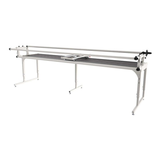
- Page 1 12 Foot Frame - Assembly & Use Just purchased your frame? Save time setting it up by following the instructions in this manual! Copyright September 18, 2020 Grace Company (Reproduction Prohibited) Version 1.0...
-
Page 2: Table Of Contents
Contents Included Parts & Tools ..................3 Extended Frame Assembly ................4 Step 1 - Setting the Frame Height ......................5 Step 2 - Building the Frame Table ......................7 Step 3 - Installing the Tracks ......................12 Step 4 - Assembling the Rail Supports ....................16 Step 5 - Installing the Bottom Carriage .................... -
Page 3: Included Parts & Tools
Included Parts & Tools Please make sure all pieces are included in your kit. Middle Leg 2 ft Table Section CII-09-14523 CII-09-14639 See page 5, 47 See page 7, 42 2 ft Rail Sections (x3) Track Support Middle Leg Brace (x2) Connector (x2) CII-04-11397 CNT-04-11041... -
Page 4: Extended Frame Assembly
Extended Frame Assembly This section describes the steps for setting up the frame if the base frame has not yet been assembled. For steps on extending a frame that has already been set up, see “Upgrade Existing Frame” on page 38. Tip: For additional help, scan the QR code below with the camera on your smart phone to visit our online support videos! https://www.graceframe.com/en/resources/support/videos... -
Page 5: Step 1 - Setting The Frame Height
Extended Frame Assembly Step 1 - Setting the Frame Height Parts & Tools Needed: Left Leg Right Leg Allen Wrench 5 mm Middle Leg (x2) From Base Frame Extension Box From Base Frame From Base Frame & Extension Box Open-ended Wrench T-Handle Allen 10 mm &... - Page 6 Extended Frame Assembly Setting the Frame Height (Continued) On all legs: Re-tighten the set screws with On all legs: Raise the top of the leg until the 4 mm Allen wrench. The middle leg has the leg is the desired height. Re-install the only one set screw.
-
Page 7: Step 2 - Building The Frame Table
Extended Frame Assembly Step 2 - Building the Frame Table Parts & Tools Needed: Table Section 2ft T-Handle Allen Table Section (x2) Left Leg Wrench 4 mm Extension Box From Base Frame SBHCS Screw Allen Wrench 5 mm Middle Leg (x2) Corner Brace (x4) M8 x 16 mm (x40) From Base Frame... - Page 8 Extended Frame Assembly Building the Frame Table (Continued) Use two M8 x 16 mm SBHCS screws to attach the left frame leg to the underside of one of the long table sections. Tighten with the 5 mm Allen wrench. Long Table Left Frame Leg Section M8 x 16 mm...
- Page 9 Extended Frame Assembly Building the Frame Table (Continued) Carefully lift the table to a standing position. Use two M8 x 16 mm SBHCS screws to attach the right frame leg to the underside of the remaining table section. Tighten with the 5 mm Allen wrench. Right Frame Table Section M8 x 16 mm...
- Page 10 Extended Frame Assembly Building the Frame Table (Continued) Attach one of the corner braces to the top right corner of the frame with the 5 mm Allen wrench and four M8 x 16 mm SBHCS screws. M8 x 16 mm SBHCS (x4) Corner Brace Note: Keep table and leg as square as possible while attaching brace.
- Page 11 Extended Frame Assembly Building the Frame Table (Continued) Attach the 2ft table section to the middle legs using four M8 x 16 mm SBHCS screws and the 5 mm Allen wrench. Install a middle brace onto the front and back of both middle legs with six M8 x 16 mm SBHCS screws each and the 5 mm Allen wrench.
-
Page 12: Step 3 - Installing The Tracks
Extended Frame Assembly Step 3 - Installing the Tracks Parts & Tools Needed: 12 Foot Plastic Track Support Set Screw Allen Wrench 3 mm Track (x4) Connector (x4) M6 x 6 mm (x16) Base Frame Base Frame Extension Box Extension Box &... - Page 13 Extended Frame Assembly Installing the Tracks (Continued) Slide a short track support onto the track connector. Short Track Support Track Connector Use two M6 x 6 mm set screws and the 3 mm Allen wrench to tighten the track support firmly to the connector.
- Page 14 Installing the Tracks (Continued) Attach another long track support to the assembly using the track connector and two M6 x 6 mm set screws. M6 x 6 mm Set Screws (x2) Long Track Support Thread each of the plastic tracks into the track supports. Repeat steps 1–7 with the remaining parts.
- Page 15 Extended Frame Assembly Installing the Tracks (Continued) Line up the front track support as close to the edge of the frame as possible and tighten the connector bolts. Front Track Support Carefully place the bottom carriage onto the frame. Bottom Carriage Slowly slide the carriage from one side of the frame to the other.
-
Page 16: Step 4 - Assembling The Rail Supports
Extended Frame Assembly Step 4 - Assembling the Rail Supports Parts & Tools Needed: SBHCS Screw Allen Wrench 5 mm M8 x 55 mm (x8) Base Frame Front Rail Arm Front Rail Arm Take-Up Rail Arm Take-Up Rail Arm (Non-Ratcheting) (Ratcheting) (Non-Ratcheting) (Ratcheting) -
Page 17: Step 5 - Installing The Bottom Carriage
Extended Frame Assembly Step 5 - Installing the Bottom Carriage Parts & Tools Needed: Channel Lock (x1) Channel Lock T-Handle Allen Bottom Carriage Washer (x1) Wrench 4 mm Base Frame Base Frame SBHCS Screw M6 x 20 mm (x1) Base Frame Instructions Install a channel lock on the bottom carriage before placing the bottom carriage onto the frame. - Page 18 Extended Frame Assembly Installing the Bottom Carriage (Continued) Remove the screw attaching the outside, Screw the channel lock and washer onto right-rear wheel to the bottom carriage the right-rear bottom carriage wheel with an M6 x 20 mm SBHCS and 4 mm Allen using the 4 mm Allen wrench.
-
Page 19: Step 6 - Installing The Quilting Machine
Extended Frame Assembly Step 6 - Installing the Quilting Machine If using a top carriage and home sewing machine, please follow the instructions Parts & Tools Needed: in your top carriage manual and then go to page 21. T-Handle Allen SBHCS Screw Channel Lock Channel Lock (x1) - Page 20 Extended Frame Assembly Installing the Quilting Machine (Continued) With the channel lock in the open position, carefully place machine onto the bottom carriage, if not already done.
-
Page 21: Step 7 - Leveling The Frame
Extended Frame Assembly Step 7 - Leveling the Frame Parts & Tools Needed: Open-End Wrench 14 mm & 17 mm Base Frame Instructions Leveling the frame ensures the machine doesn’t drift or pull to one side when stitching. Move the machine and bottom carriage to one corner of the frame, and release. If the machine rolls away from the corner, use the 17 mm open-end wrench to adjust the leveling foot at the bottom of the leg. - Page 22 Extended Frame Assembly Leveling the Frame (Continued) Test the next corner of the frame, and adjust the leveling foot underneath if Leveling Foot Adjustment needed. Loosen the top nut on the leveling foot with the 17 mm open-end wrench. Test the middle of the frame next, and then the other two corners.
-
Page 23: Step 8 - Installing The Rails
Extended Frame Assembly Step 8 - Installing the Rails Parts & Tools Needed: Ratchet Rail Section (x2) Base Frame Non-ratchet Rail Section (x3) Base Frame Handwheel Rail Section Base Frame T-Handle Allen Rail Coupler (x6) 2 ft Rail Sections (x3) Wrench 4 mm Extension Box Base Frame... - Page 24 Extended Frame Assembly Installing the Rails (Continued) Use the 4 mm Allen wrench to loosen (turn counter-clockwise) the coupler screws inside the rail until they press firmly against the rail. Slide one of the 2 ft rail sections onto the other side of the rail coupler. 2 ft Rail Section Line up the coupler screws with the holes in the rail and loosen them with the 4 mm Allen wrench until they press firmly against the inside of the rail.
- Page 25 Extended Frame Assembly Installing the Rails (Continued) Now insert a second coupler into the 2 ft rail section. Rail Coupler Once again, loosen the screws with the 4 mm Allen wrench until the rail and coupler are snug. Slide one of the ratcheting rail sections onto the other side of the rail coupler. Ratchet Rail Section...
- Page 26 Extended Frame Assembly Installing the Rails (Continued) Line the coupler screws with the holes in the rail and loosen them with the 4 mm Allen wrench until they press firmly against the inside of the rail. Repeat steps 1-8 with the remaining rails. One rail will be completed with the handwheel rail section in place of the ratcheting rail section.
- Page 27 Extended Frame Assembly Installing the Rails (Continued) Press the other end of the rail into the front rail arm (non-ratcheting side). Front Rail Arm (Non-ratcheting) Non-ratchet Rail Repeat steps 10-11 for the bottom rail. Insert the handwheel rail through the throat of the machine. Handwheel Rail...
- Page 28 Extended Frame Assembly Installing the Rails (Continued) Place the ratcheting side of the rail into the ratcheting take-up rail arm, and then press the non-ratcheting side into the non-ratcheting take-up rail arm.
-
Page 29: Step 9 - Assembling The Handwheel
Extended Frame Assembly Extended Frame Assembly Step 9 - Assembling the Handwheel Parts & Tools Needed: Handwheel Handwheel Knob Allen Wrench 6 mm Three-Armed Handwheel Knob Base Frame Base Frame Base Frame Base Frame Shoulder Bolt M8 x 55 mm SBHCS Base Frame Handwheel Coupler M10 Washer... -
Page 30: Step 10 - Installing The Bungee Clamps
Extended Frame Assembly Extended Frame Assembly Step 10 - Installing the Bungee Clamps Parts & Tools Needed: Bungee Clamp (x4) Base Frame Instructions The bungee clamps hold the edges of the quilt up and provide additional tension to the quilt surface. Take the following steps: Note: Your bungee clamps may have come Repeat step 2 to install all four bungee... -
Page 31: Step 11 - Adjusting The Rails
Extended Frame Assembly Extended Frame Assembly Step 11 - Adjusting the Rails Parts & Tools Needed: T-Handle Allen Wrench 4 mm Instructions The placement of the rails in relation to the machine is crucial for proper quilt alignment and quality sewing. - Page 32 Extended Frame Assembly Adjusting the Rails (Continued) To set the front rail height, turn the knobs on the necks of both front rail arms. Press in the levers to raise or lower the front rail. Set the top of the rail so it is level with the machine’s needle plate.
-
Page 33: Step 12 - Installing The Velcro Tape
Extended Frame Assembly Step 12 - Installing the Velcro Tape Parts & Tools Needed: Leader Cloth Set Marker (not included) Tape Measure (not included) Extension Box Velcro Tape (x3) (found in leader cloth set) Instructions Velcro strips are used to attach the leader cloth to your frame. The leader cloths help align the quilt and maximize the area of the quilt surface that the machine will be able to reach. - Page 34 Extended Frame Assembly Installing the Velcro Tape (Continued) On all three rails: Lay a tape measure flat across the rail, aligning it with the holes on the top. Find and mark the center point. Measuring Tape Remove some of the backing from the center of the tape and attach the tape to center of one of the rails.
- Page 35 Extended Frame Assembly Installing the Velcro Tape (Continued) Start from the center and carefully peel away the backing of the tape, flattening as you go. Note: Image showing base setup. Step is the same for the extended frame. Now do the same for the other side of the rail. Note: Image showing base setup.
-
Page 36: Step 13 - Installing Leader Cloth
Extended Frame Assembly Step 13 - Installing Leader Cloth Parts & Tools Needed: Leader Cloth Set Tape Measure (not included) Marker (not included) Instructions The leader cloths attach the quit to the frame while maximizing the quilt surface that the machine can reach. - Page 37 Extended Frame Assembly Installing the Leader Cloth (Continued) Moving from the center outward, smooth the top edge of the leader cloth across the Velcro. Note: Image showing base setup. Step is the same for the extended frame. Repeat steps 3–4 for the medium width leader cloth on the backing rail. Medium Width Leader Cloth (right side to the rear) Backing Rail...
-
Page 38: Upgrade Existing Frame
Upgrade Existing Frame If your base frame has already been set up, you will have to partially disassemble it in order to install the extension accessories. This section describes the most efficient steps for installing the two foot extension. If your base frame has not already been set up, go to the “Extended Frame Assembly” on page 4. Tip: For additional help, scan the QR code below with the camera on your smart phone to visit our online support videos! https://www.graceframe.com/en/resources/support/videos... -
Page 39: Step 1 - Rail Assembly
Upgrade Existing Frame Step 1 - Rail Assembly Parts & Tools Needed: T-Handle Allen 2 ft Rail Sections (x3) Rail Coupler (x3) Wrench 4 mm Instructions The base frame must be partially deconstructed in order to properly install the 2 foot extension. Please take the following steps: Remove fabric and all three leader cloths from the frame. - Page 40 Upgrade Existing Frame Rail Assembly (Continued) Uninstall the three rails. Handwheel Coupler Washer Rail (x3) 3 Armed Handwheel Knob Note: Unscrew the 3 Armed handwheel knob to remove the take-up rail. Turn the six screws on the non-ratcheting rail sections clockwise with a 4 mm Allen wrench to separate the rail sections from the rail coupler.
- Page 41 Upgrade Existing Frame Rail Assembly (Continued) Slide each of the 2 foot rail sections onto the rail couplers. Turn the screws counter-clockwise with the 4 mm Allen wrench. 2 Ft Rail Section (x3) Install the remaining rail couplers into the other end of the two foot section using the 4 mm Allen wrench.
-
Page 42: Step 2 - Track Assembly
Upgrade Existing Frame Step 2 - Track Assembly Parts & Tools Needed: Plastic Track T-Handle Allen Allen Wrench 3 mm Table Section 2ft 12 ft (x4) Wrench 4 mm Track Support Set Screw Connector (x2) M6 x 6 mm (x8) Instructions The base frame must be partially deconstructed in order to properly install the 2 foot extension. - Page 43 Upgrade Existing Frame Track Assembly (Continued) Use a 4 mm Allen wrench to remove the connector bolts and track supports from the frame. Track Support (x2) Connector Bolts (x16) On both track supports: Remove the plastic tracks. Plastic Track (x2) Track Support On both track supports: Use a 3 mm Allen wrench to remove the two M6 x 6 mm set screws from one side of the support.
- Page 44 Upgrade Existing Frame Track Assembly (Continued) On both track supports: Separate the two halves. Use a 4 mm Allen Wrench to remove the connector bolts and track supports from 2 foot table section. Track Support (x2) 2 ft Table Section Connector Bolts (x4) On both long track supports with the track coupler: Install the two foot track support...
- Page 45 Upgrade Existing Frame Track Assembly (Continued) On both track supports: Use two M6 x 6 mm set screws and the 3 mm Allen wrench to tighten the track support firmly to the connector. Set Screw M6 x 6 mm (x2) Track Connector On both track supports: Slide a long track support into the free end of the track connector.
- Page 46 Upgrade Existing Frame Track Assembly (Continued) On both track supports: Thread each of the 12 foot plastic tracks into the track supports. 12 ft Plastic Track (x2) Track Support...
-
Page 47: Step 3 - Extending The Table
Upgrade Existing Frame Step 3 - Extending the Table Parts & Tools Needed: Allen Wrench 5 mm Middle Leg SBHCS Screw Table Section 2ft M8 x 16 mm (x20) Middle Leg Brace (x2) Instructions Take the following steps to install the 2 foot extension to the base frame: Remove the six M8 x 16 mm SBHCS holding the right side of the frame to the middle braces. - Page 48 Upgrade Existing Frame Extending the Table (Continued) Carefully pull the right side of the frame away from the middle leg. Use two M8 x 16 mm SBHCS and the 5 mm Allen wrench to attach the second middle leg to the table frame.
- Page 49 Upgrade Existing Frame Extending the Table (Continued) Place the 2 ft table section onto the middle legs. 2 ft Table Section Secure the table section to the legs with four M8 x 16 mm SBHCS screws and the 5 mm Allen wrench.
- Page 50 Upgrade Existing Frame Extending the Table (Continued) Re-install the six M8 x 16 mm SBHCS that were removed from the middle braces in step 3.1. M8 x 16 mm SBHCS (x6) Install the remaining middle leg braces onto the frame with twelve M8 x 16 mm SBHCS screws and the 5 mm Allen wrench.
-
Page 51: Step 4 - Installing The Tracks
Upgrade Existing Frame Step 4 - Installing the Tracks Parts & Tools Needed: T-Handle Allen Wrench 4 mm Instructions Take the following steps to install and align the frame tracks: Loosely connect the track supports to the frame with the 4 mm Allen wrench and the twenty M6 x 10 mm connector bolts removed in “Step 2 - Track Assembly”... - Page 52 Upgrade Existing Frame Installing the Tracks (Continued) Slowly slide the carriage from one side of the frame to the other. Tighten each of the ten rear connector bolts as the bottom carriage passes over them. Connector Bolts (x10)
-
Page 53: Step 5 - Leveling The Frame
Upgrade Existing Frame Step 5 - Leveling the Frame Parts & Tools Needed: Open-End Wrench 14 mm & 17 mm Base Frame Instructions Leveling the frame ensures the machine doesn’t drift or pull to one side when stitching. Move the machine and bottom carriage to one corner of the frame, and release. If the machine rolls away from the corner, use the 17 mm open-end wrench to adjust the leveling foot at the bottom of the leg. - Page 54 Upgrade Existing Frame Leveling the Frame (Continued) Test the next corner of the frame, and adjust the leveling foot underneath if Leveling Foot Adjustment needed. Loosen the top nut on the leveling foot with the 17 mm open-end wrench. Test the middle of the frame next, and then the other two corners.
-
Page 55: Step 6 - Installing The Rails
Upgrade Existing Frame Step 6 - Installing the Rails Instructions Please take the following steps to install the frame rails: Insert the ratchet section end of one of the rails into the front rail arm (ratcheting side). Front Rail Arm (Ratcheting) Ratchet Section Press the other end of the rail (the non-ratchet rail side) into the front rail arm (non-... - Page 56 Upgrade Existing Frame Installing the Rails (Continued) Insert the take-up rail handwheel side first through the throat of the machine. Take-up Rail Place the ratcheting side of the rail into the ratcheting take-up rail arm, and then press the non-ratcheting side into the non-ratcheting take-up rail arm. Screw the handwheel coupler, handwheel, washer, and three-armed handwheel knob to the take-up rail.
-
Page 57: Step 7 - Adjusting The Rails
Upgrade Existing Frame Step 7 - Adjusting the Rails Parts & Tools Needed: T-Handle Allen Wrench 4 mm Instructions The placement of the rails in relation to the machine is crucial for proper quilt alignment and quality sewing. For customers using the idler or batting accessory rails, please refer to the instructions that came with your accessories on how to configure your rails. - Page 58 Upgrade Existing Frame Adjusting the Rails (Continued) To set the front rail height, turn the knobs on the necks of both front rail arms. Press in the levers to raise or lower the front rail. Set the top of the rail so it is level with the machine’s needle plate.
-
Page 59: Step 8 - Installing The Velcro Tape
Upgrade Existing Frame Step 8 - Installing the Velcro Tape Parts & Tools Needed: Leader Cloth Set Marker (not included) Tape Measure (not included) Velcro Tape (x3) (found in leader cloth set) Instructions Velcro strips are used to attach the leader cloth to your frame. The leader cloths help align the quilt and maximize the are of the quilt surface that the machine will be able to reach. - Page 60 Upgrade Existing Frame Installing the Velcro Tape (Continued) On all three rails: Lay a tape measure flat across the rail, aligning it with the holes on the top. Find and mark the center point. Measuring Tape Remove some of the backing from the center of the tape and attach the tape to center of one of the rails.
- Page 61 Upgrade Existing Frame Installing the Velcro Tape (Continued) Start from the center and carefully peel away the backing of the tape, flattening as you go. Note: Image showing base setup. Step is the same for the extended frame. Now do the same for the other side of the rail. Note: Image showing base setup.
-
Page 62: Step 9 - Installing Leader Cloth
Upgrade Existing Frame Step 9 - Installing Leader Cloth Parts & Tools Needed: Leader Cloths Tape Measure (not included) Marker (not included) Instructions The leader cloths attach the quit to the frame while maximizing the quilt surface that the machine can reach. - Page 63 Upgrade Existing Frame Installing the Leader Cloth (Continued) Moving from the center outward, smooth the top edge of the leader cloth across the Velcro. Note: Image showing base setup. Step is the same for the extended frame. Repeat steps 3–4 for the medium width leader cloth on the backing rail. Medium Width Leader Cloth (right side to the rear) Backing Rail...
-
Page 64: Using Your Frame
Using Your Frame This section describes how to attach fabric and how to use the channel locks. -
Page 65: Sizing The Quilt Backing And Batting
Using Your Frame Sizing the Quilt Backing and Batting Parts & Tools Needed: Pins (not included) Fabric (not included) Tape Measure (not included) Instructions The quilt backing and batting must be properly sized for neat quilting. Measure the length and width of your quilt Cut your quilt backing so it is 6-8 inches top. -
Page 66: Attaching The Fabric
Using Your Frame Attaching the Fabric Parts & Tools Needed: Pins (not included) Fabric (not included) Instructions Take the following steps to properly mount your quilt on the frame: Fold your quilt’s backing in half to find the Work from the center out and pin the center. - Page 67 Using Your Frame Attaching the Fabric (Continued) Fold your batting to locate the top center- Pin the top center-point of your quilt point. Place a pin to mark it. backing to the center-point on the take- up rail leader cloth. Top Center- point Take-up rail...
- Page 68 Using Your Frame Attaching the Fabric (Continued) Drape the bottom of the batting between Pin down the top of the quilt from the the backing and top rails. center out. Backing Rail Top Rail Fold your quilt top to locate the top Pin the bottom of the quilt top to the center-point.
- Page 69 Using Your Frame Attaching the Fabric (Continued) To hold up the edges of the quilt, slide the fabric into the bungee clamps. Tension by pressing down on the bungee stops and pulling the bungee tail. Roll up your quilt as you go. Turn the top knobs on the front rails to release the quilt tension.
-
Page 70: Using The Channel Locks
Using Your Frame Using the Channel Locks Instructions The channel locks assist with stitching in a straight line by inhibiting the movement of the bottom carriage or machine. On both channel locks: Flip down the arm On both channel locks: To prevent the on the machine channel lock to close the rubber foot from loosening over time, use channel lock. - Page 71 Using Your Frame Using the Channel Locks (Continued) To move the machine back and forth on the bottom carriage and create a straight vertical line, close only the bottom carriage channel lock. To move the machine across the frame and create a straight horizontal line, close only the channel lock on the machine.
- Page 72 The Grace Company 2225 South 3200 West Salt Lake City, UT 84119 Phone: 1-800-264-0644 Fax: 801-908-8888 www.graceframe.com...
Need help?
Do you have a question about the Continuum II and is the answer not in the manual?
Questions and answers