Table of Contents
Advertisement
Quick Links
Black & Shield
White
Green
1
2
3
4
5
6
7
8
9
10
11
12
13
14
15
16
17
18
19
20
21
22
23
24
Note: Make sure that terminal 4 is connected to 6 and termnial 13 is connected to 15 (see figure) in order to enable the corresponding relay
outputs 1 & 2. This contact is particularly useful for enabling, for instance, the relay outputs of the M2000PE via external devices such as buried
magnetic coils (opening command given by the M2000PE only in case of a vehicle being present on the coil so as to avoid undesired opening caused
by accidental radio transmission) or via timed relays (M2000PE enabled within a given time interval), as well as for closing the normally open contact
of a switch, and so on.
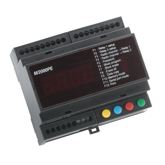
Diagram of terminal strips and keys
Red
18 17 16 15 14 13 12 11 10
M/2000PE
M/2000E
19 20 21 22 23 24
Port 2 – Relay Normally Closed
Port 2 – Relay Common
Port 2 – Relay Normally Open
Port 2 – Relay Enabling Contact
Port 2 – Relay Activation (when linked to ground)
Ground
Port 2 – Data Input (DATA 1)
Port 2 – Data Input (DATA 0)
Port 2 – Output for reader power supply (9vdc)
Port 1 – Relay Normally Closed
Port 1 – Relay Common
Port 1 – Relay Normally Open
Port 1 – Relay Enabling Contact
Port 1 – Relay Activation (when linked to ground)
Ground
Port 1 – Data Input (DATA 1)
Port 1 – Data Input (DATA 0)
Port 1 – Output for reader power supply (9vdc)
Antenna Core
Antenna Braid
Serial Line (RS485)
Serial Line (RS485)
Power Supply + 12/24V ac/dc
Power Supply – 12/24V ac/dc
Green
White
Black & Shield
9
8
7
6
5
4
3
2
1
F1
: Relay 1 setup
F2
: Relay 2 setup
F3
: Radio channel - Relay 1
F4
: Radio channel - Relay 2
F5
: Password
F6
: Block program
F7
: Block erase
F8
: Erase all
F9
: Data copy
F10
: Memory mode
F11
: Serial port mode
F12
: Print
FUN
DEC
INC
VAL
YELLOW BLUE
RED
GREEN
Red
Normally Open
Common
Normally Closed
Advertisement
Table of Contents

Related Manuals for PRASTEL M2000PE


Summary of Contents for PRASTEL M2000PE
- Page 1 1 & 2. This contact is particularly useful for enabling, for instance, the relay outputs of the M2000PE via external devices such as buried magnetic coils (opening command given by the M2000PE only in case of a vehicle being present on the coil so as to avoid undesired opening caused by accidental radio transmission) or via timed relays (M2000PE enabled within a given time interval), as well as for closing the normally open contact of a switch, and so on.
- Page 2 All operations can also be performed through the remote M/KEYB keyboard/display connected to the unit via RS/485. All M2000PE circuits and components are housed in a plastic enclosure suitable for indoor installation and for mounting on bars according to DIN standards.
- Page 3 After selection of the final location, confirm by pressing the GREEN button. The M2000PE will now set itself up to accept transmission of a code. Once code has been received (via radio or any of the connected readers), it is entered in the initial location. All subsequent locations up to the final one may be entered with codes obtained by increasing the initial code by one unit.
- Page 4 The printer PRINT200 must have been previously programmed with the correct date and time. Operating the system via the remote keyboard The M2000PE may be connected to a terminal equipped with 4 keys and 4 displays for the remote programming, entering and deleting of codes. Communication is made via an RS485 serial line.
Need help?
Do you have a question about the M2000PE and is the answer not in the manual?
Questions and answers