Table of Contents
Advertisement
Quick Links
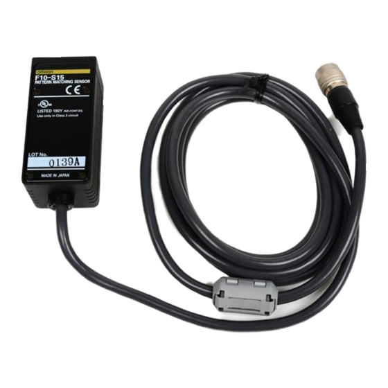
Pattern Matching Sensor
Ordering Information
Heads
Item
Red LED
Green LED
Green LED
Amplifiers
Type
Standard models
Models with bank function
Models with RS-232C and
RS-422 interfaces
Cables
Type
RS-232C (cable length: 2 m)
RS-422 (cable length: 2 m)
Setting distance
Output
NPN
PNP
NPN
PNP
NPN
PNP
Model
F10-VR2
F10-VR4
Detection range
40 × 32 mm
160±16 mm
25 × 20 mm
100±10 mm
12 × 10 mm
50±5 mm
4.5 × 3.5 mm
33±1.5 mm
No. of registered models
1
8 (one model per bank)
F10
Model
F10-S50R
F10-S30R
F10-S15R
F10-S05R
Model
F10-C20
F10-C25
F10-C30
F10-C35
F10-C50
F10-C55
1
Advertisement
Table of Contents

Related Manuals for Omron F10 Series


Summary of Contents for Omron F10 Series
- Page 1 Pattern Matching Sensor Ordering Information Heads Item Setting distance Detection range Model 40 × 32 mm Red LED 160±16 mm F10-S50R 25 × 20 mm 100±10 mm F10-S30R 12 × 10 mm Green LED 50±5 mm F10-S15R 4.5 × 3.5 mm Green LED 33±1.5 mm F10-S05R...
-
Page 2: Specifications
Specifications Ratings/Characteristics Heads Optical and Lighting System Specifications Item Specifications F10-S50R F10-S30R F10-S15R F10-S05R Setting distance 160±16 mm 100±10 mm 50±5 mm 33±1.5 mm 40 mm × 32 mm 25 mm × 20 mm 12 mm × 10 mm 4.5 mm × 3.5 mm Detection range Guide light projection size A: 40 mm... - Page 3 Amplifiers Performance Specifications Item Specification Model F10-C20/C30/C50 F10-C25/C35/C55 Output type Measurement item Pattern measurement/plain measurement Number of models C20/C25: 1 model, C30/C35/C50/C55: 1 model per bank Bank selection C20/C25: None, C30/C35/C50/C55: 8 banks Automatic teaching function Model size Normal or wide mode (selectable) Measurement processing 3.6 ms in normal mode and 10.8 ms in wide mode (continuous operation) time...
-
Page 4: Engineering Data
Engineering Data Data Characteristics F10-S50R • Rotation The following data is obtained on the basis of sample sensing objects, each of which is as large as this size (A). (Typical example) • The Head is inclined 15° to the sensing object. - Page 5 F10-S15R • Rotation The following data is obtained on the basis of sample sensing objects, each of which is as large as this size (A). (Typical example) • The Head is inclined 15° to the sensing object. Shift angle Area Position Characteristics Area Position Characteristics Rotation Characteristics (in X Direction)
- Page 6 Nomenclature Heads F10-S50R Teaching area Guide light (green) 13 mm F10-S50R with 2-m standard cable Object lighting (red) 160±16 mm 40 mm Sensing side Detection range (field of vision) F10-S30R Teaching area Guide light (green) Object lighting (red) F10-S30R with 2-m standard cable 100±10 mm Detection range (field of vision) Sensing side...
- Page 7 Amplifiers F10-C20/C25 F10-C30/C35/C50/C55 (2) Result (2) Result (1) Level (1) Level indicator indicator indicators indicators (4) Status (4) Status indi- (3) Threshold (3) Threshold indicators cator/bank indicators indicators number display (5) Teach/ (5) Teach/ display display button (6) UP/DOWN (6) UP/DOWN button selection selection...
- Page 8 (9) DIP Switch All the DIP switch pins are set to OFF at the factory. Automatic Teaching A.T. ON: Teaching area automatically selected A.T. OFF: Teaching area fixed A.T. ON Most Automatically selects the pattern most suitable suitable for the model. The part within the detection range where the deviation level between the background and the target is Too pale...
-
Page 9: Installation
Installation Mounting Angle • Incline the Head by 15° and mount the Head so that no regular reflection light affects the Sensor. • Use the provided Mounting Bracket to mount the Head. Simulation Sensor direction F10-S50R 15° 15° F10-S30R F10-S15R F10-S30R: 100±10 mm F10-S05R F10-S15R: 50±5 mm... -
Page 10: Multidrop Connections
Multidrop Connections A maximum of 31 F10-C50/C55 Sensors can communicate with an IBM PC/AT or compatible by connecting though RS-232C/422 converters. Recommended Link Adapters (manufactured by OMRON) Link Adapter: B500-AL004 Branching Link Adapter: B500-AL001 Note: When using a B500-AL004 Branching Link Adapter, be sure to enable terminating resistance and include a terminating resistance in the last link adapter according to the following: Between RDA(–) and RDB(+): 220 Ω... -
Page 11: Operation
Operation I/O Circuit Diagram F10-C20 NPN Models F10-C25 PNP Models There are gray, green, and red input lines, but they are not used with There are gray, green, and red input lines, but they are not used with this model. Take steps to ensure that these lines will not be short-cir- this model. -
Page 12: Setting Procedure
Setting Procedure 1. Pattern Registration (TEACH Mode) Use the following procedure to register measurement criteria. (1) Set the mode selector to TEACH. (2) Make the automatic teaching and model size settings on the DIP switch. If using an F10-C30/C35/C50/C55, go to step (3) to set the bank number. If using an F10-C20/C25, go to step (5). (3) Set the measurement item/bank number selection switch to PATT/BANK. - Page 13 Teaching is performed in the teaching area. A pat- OMRON tern close to the edge of the detection range will not Note: 1. The detection range can be enlarged. Refer to the...
- Page 14 Plain Measurement Press the teach/display button to change the display (DEV-AVE). • Status indicators (F10-C20/C25) PATT DEV lit Deviation level Deviation Plain measurement level is Difference from average small density during teaching • Status indicator (F10-C30/C35/C50/C55) Plain measurement Deviation level is Increases the smaller great DEV (deviation level)
- Page 15 3. Performing Measurement in Response to External Input Signals (RUN Mode) (1) Set the mode selector to RUN. When the switch is set to RUN mode, measurements are made in response to external input signals. Relationship between the F10 I/O terminal operations and ON/OFF indications in the timing charts are as shown in the following table. Signal Indication in timing charts NPN (F10-C20/C30/C50)
-
Page 16: Enable Output
External Teaching in RUN Mode In RUN mode, a model can be registered by external signal input using either of the following methods. Note: The data of the model is stored in the EEPROM when the teaching process of the Sensor completes. Therefore, do not turn OFF the Sensor during the teaching process. -
Page 17: Troubleshooting
Head may be broken. Consult your OMRON representative. This threshold indicator flashes and the buzzer sounds. Hardware error Consult your OMRON representative. A hardware failure, such as CPU runaway, Buzzer has resulted. sounds This threshold indicator flashes and the buzzer sounds. - Page 18 Note: If the output does not turn ON even triggered. after reducing the current below the rated value, contact your OMRON representative. Dimensions Note: All units are in millimeters unless otherwise indicated. Amplifiers...
-
Page 19: Mounting Bracket
Heads F10-SjR The Mounting Bracket can be attached to this side as well. Ferrite core (75) 14.7-dia. connector (125) 5.8-dia. Vinyl-insulated round cable, standard length: 2 m Mounting hole Mounting hole 2-M4 pan-head screw (16.7) Mounting Dimensions Two, M4 37±0.2 Mounting Bracket Protruding part R1 max. -
Page 20: General Precautions
Precautions Setup Others The F10-Cj Amplifier radiates heat. If more than one Unit is Application Precautions installed side-by-side, make sure that there is a minimum space of 5 mm between adjacent Units as shown below. Caution 5 mm min. Do not make mistakes in wiring, such as mistakes in polarity. Doing so may cause Sensor damage or malfunction. - Page 21 The product has been produced at OMRON Ayabe which obtained ISO9001-approval for its quality system and ISO14001-approval for its environmental management system from international certification bodies. ALL DIMENSIONS SHOWN ARE IN MILLIMETERS. To convert millimeters into inches, multiply by 0.03937. To convert grams into ounces, multiply by 0.03527.
Need help?
Do you have a question about the F10 Series and is the answer not in the manual?
Questions and answers