Table of Contents
Advertisement
Quick Links
Installation Manual
Pro1 Technologies
P.O. Box 3377
Springfield, MO 65808-3377
Toll Free: 888-776-1427
Web: www.pro1iaq.com
Hours of Operation: M-F 9AM - 6PM Eastern
Thermostat Application Guide
Description
Gas or Oil Heat
Electric Furnace
Heat Pump (No Aux. or Emergency Heat)
Heat Pump (With Aux. or Emergency Heat)
Multi-Stage Systems
Heat Only Systems
Cool Only Systems
Millivolt
Wired Remote Sensing
Any HVAC system up to 5H/3C with
standard low voltage controlled humidifier.
Any HVAC system up to 5H/3C with standard
low voltage controlled de-humidifier.
Table of Contents
Installation Tips
WIFI Tech Settings
U.S. Registered Trademark. Patents pending
1
Copyright
2020 All Rights Reserved.
Installation Tips
Subbase Installation
Horizontal Mount
Vertical Mount
Installation Tip: Electrical Hazard
Failure to disconnect the power before beginning to install this product
can cause electrical shock or equipment damage.
Mercury Notice
All of our products are mercury free. However, if the product you are
replacing contains mercury, dispose of it properly. Your local waste
management authority can give you instructions on recycling and
proper disposal.
3
T855iSH
Power Type
Hardwire (Common Wire)
Yes
Yes
Yes
Yes
Yes
A trained, experienced
Yes
technician must install this
Yes
product.
No
Yes
Carefully read these
instructions. You could damage
Yes
this product or cause a
Yes
hazardous condition if you fail
to follow these instructions.
Page
Una version en espanol de este
manual se puede descargar en
2-4
la pagina web de la compania.
5-8
9-10
11-14
15-33
34
35-37
38-43
44
45
46
For horizontal mount put one screw on
the left and one screw on the right.
For vertical mount put one screw on
the top and one screw on the bottom.
Installation Tips
Wall Locations
The thermostat should be installed approximately 4 to 5 feet above the
floor. Select an area with average temperature and good air circulation.
Do not install thermostat in these locations:
• Close to hot or cold air ducts
• That are in direct sunlight
• With an outside wall behind the thermostat
• In areas that do not require conditioning
• Where there are dead spots or drafts (in corners or behind doors)
• Where there might be concealed chimneys or pipes
Installation Tip
Pick an installation location that is easy for the user to access. The temperature
of the location should be representative of the building.
Rev. 2028
Installation Tips
Mount Thermostat
Align the 4 tabs on the subbase with
corresponding slots on the back of the
thermostat, then push gently until the
thermostat snaps in place.
Note: To ensure a solid fit between the
thermostat and the subbase:
1. Mount subbase to a flat wall
2. Use screws provided
3. Drywall anchors should be flush with the wall
4. Wires should be pushed into the wall
2
4
Advertisement
Table of Contents

Related Manuals for Pro1 Technologies T855iSH


Summary of Contents for Pro1 Technologies T855iSH
-
Page 1: Table Of Contents
Installation Manual Installation Tips T855iSH Wall Locations The thermostat should be installed approximately 4 to 5 feet above the floor. Select an area with average temperature and good air circulation. Pro1 Technologies P.O. Box 3377 Springfield, MO 65808-3377 Toll Free: 888-776-1427 Web: www.pro1iaq.com... -
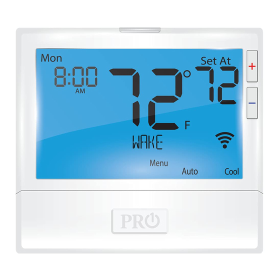
Page 2: Thermostat Quick Reference
Thermostat Quick Reference Thermostat Quick Reference Getting to know your thermostat Getting to know your thermostat Day of the Week Setpoint Indicator: Displays the user selectable setpoint temperature. Time of Day / Outdoor Temp / % Humidity Indicates current room temperature Indicates if heating or cooling equipment is running Energy Efficient Globe: Indicates the setpoint temperature chosen is a efficient choice. -
Page 3: Wiring
Wiring Wiring Terminal Designations Caution: This thermostat is shipped from the factory to operate a conventional heating Warning: and cooling system. This thermostat may also be configured for a heat pump Electrical Hazard system. See the “heat pump” configuration step on page 16 of this manual to configure the thermostat for heat pump applications. -
Page 4: Technician Setup Menu
Wiring Diagrams Wiring Diagrams A 24 VAC common connection is required with this thermostat. Power supply Factory - installed jumper. Remove only when installing on 2 transformer systems. If DEHUM relay requires a normally-energized input, set Dehumidify relay to NC in Technician Setup. - Page 5 Technician Setup Menu Technician Setup Menu Tech Setup Steps LCD Will Show Adjustment Options Default Tech Setup Steps LCD Will Show Adjustment Options Default Use the buttons Use the buttons This setting allows you to select This feature allows the thermostat 2H2C Satisfy to select 1H/1C, 2H/1C,...
- Page 6 Technician Setup Menu Technician Setup Menu Tech Setup Steps LCD Will Show Adjustment Options Default Tech Setup Steps LCD Will Show Adjustment Options Default Keypad lockout with code OFF= Code is disabled and the 0000 ˚ This feature allows you to display F for Fahrenheit creation is displayed when lock icon is used to lock and...
- Page 7 Technician Setup Menu Technician Setup Menu Tech Setup Steps Adjustment Options Default Tech Setup Steps Adjustment Options Default LCD Will Show LCD Will Show This feature allows fresh air into Use the buttons to You can disable the sensor on ON enables local T855SH select OFF, OC ON or ON.
- Page 8 Technician Setup Menu Technician Setup Menu This table references different humidity levels the thermostat will Tech Setup Steps LCD Will Show Adjustment Options Default conform to, based on the outdoor temperature measurements. This feature adds humidity when Use the key to turn on or off.
-
Page 9: Setting Humidity
Technician Setup Menu WIFI Technician Setup Menu Tech Setup Steps LCD Will Show Adjustment Options Default These steps/options are only used for trouble shooting, re-setting or restoring to default the WIFI settings of the thermostat. They are not This tech setting will select Use the buttons Summer... -
Page 10: Programming
Programming Setting the Humidity Setting Target Humidity Setpoint Set Time Follow the steps below to set the day of the week and current time: Ambient humidity will flash in the time field when Humidify or De-Humidify is set to ON. 1. -
Page 11: Features
Programming Programming To customize your 7 day 2 time period program schedule, follow Default Programming these steps: Monday: Factory Default Program 1. Select HEAT or COOL with the SYSTEM key. Setpoint Setpoint Day of Note: You have to program heat and cool each seperately. Events Time Temperature... -
Page 12: Remote Sensor Operation
Remote Sensor Operation Specifications Remote Sensor Operation Options Specifications The display range of temperature ... 41˚F to 95˚F (5˚C to 35˚C) Option #1 - Indoor / Local Temperature Sensor “ON”: The control range of temperature..44˚F to 90˚F (7˚C to 32˚C) 1.
Need help?
Do you have a question about the T855iSH and is the answer not in the manual?
Questions and answers